


Robot shaft components play an important role in transmitting motion, supporting rotating parts, and connecting mechanical components within robotic systems. Their design affects load capacity, rotational stability, wear resistance, and the reliability of moving assemblies.
This guide covers the main types of robot shaft components, their functions and applications, and the key considerations for material selection, precision machining, and custom manufacturing.
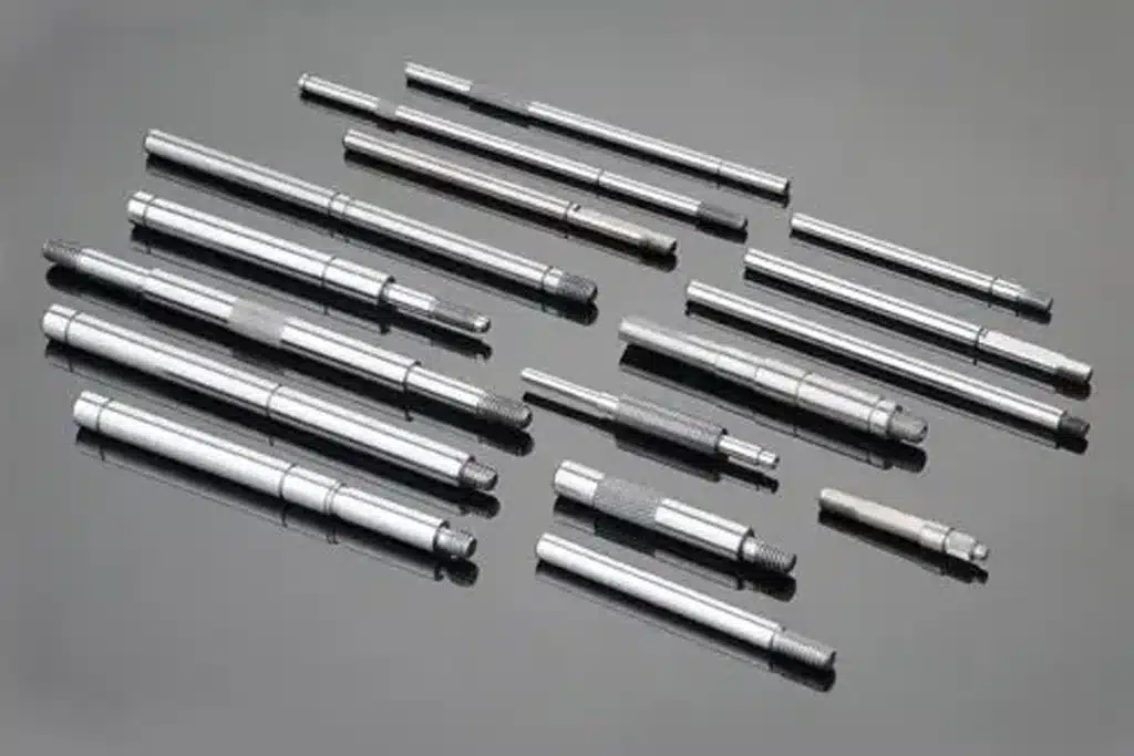
What Are Robot Shaft Components?
Definition of Robot Shaft Components
Robot shaft components are mechanical parts used in robotic systems to transmit torque, support rotating elements, maintain alignment, or connect components within a motion mechanism.
Depending on their function, these parts may serve as motor shafts, transmission shafts, output shafts, or support shafts. Their designs range from simple cylindrical shafts to stepped, hollow, splined, and other custom geometries.
Robot shafts are commonly used in joint mechanisms, drive systems, wrist assemblies, and other moving structures. Their dimensions and interfaces must match the loads, motion requirements, and connected components of the specific robotic system.
Robot Shafts vs. Robot Axes vs. Robot Joints
Although these terms are related, they describe different aspects of a robotic system.
- Robot shaft: A physical mechanical component that transmits torque, supports rotating parts, or connects mechanical elements.
- Robot axis: A controlled degree of freedom or direction of motion in a robot. Depending on the context, the term may also refer to a mechanical axis or line of rotation.
- Robot joint: A mechanical connection or assembly that allows relative movement between connected robot links, such as rotation or linear translation.
For example, a rotary robot joint may contain a motor, a reducer, bearings, and one or more shafts. The joint provides the relative motion, the robot axis describes the controlled movement, and the shaft performs a specific mechanical function within the assembly.
Understanding this distinction helps engineers identify the actual shaft components required for a design or replacement project.
Why Shaft Design Matters in Robotics
Robot shafts must withstand the loads and motion conditions of the mechanisms in which they operate. An unsuitable shaft design can lead to excessive deflection, vibration, premature wear, or problems with component alignment.
Several factors directly influence shaft performance:
- Load capacity: The shaft must withstand the required torque, bending loads, and operating cycles.
- Rotational stability: Appropriate stiffness, geometry, and support help control deflection and unwanted vibration.
- Dimensional accuracy: Critical diameters and geometric tolerances affect bearing fits, alignment, and mating interfaces.
- Wear resistance: Material selection, surface condition, and any specified heat treatment influence service life.
- Structural efficiency: The shaft must balance strength, stiffness, weight, and available installation space.
Shaft accuracy alone does not determine the overall accuracy of a robot. Bearings, reducers, assembly quality, control systems, and calibration also influence system performance. The goal is to manufacture each shaft to the requirements of its specific mechanical function.

Types of Robot Shaft Components by Function
Robot shaft components can be classified by their role in a mechanism. This functional classification is different from classification by structure: for example, a shaft can be both a hollow shaft and an output shaft.
Output Shafts
Output shafts transfer rotational power from a motor, gearbox, reducer, or other drive mechanism to a connected component.
In robotic systems, an output shaft may connect to a rotating link, wrist mechanism, end-effector interface, or another driven assembly. Its design depends on the required torque, mounting arrangement, and interface with the driven component.
Key design features may include stepped diameters, mounting holes, keyways, splines, or precision bearing seats. These features must be manufactured to the specified dimensions and tolerances to ensure reliable connection and power transmission.
Transmission Shafts
Transmission shafts carry torque and rotational motion between components within a drive or transmission system.
Depending on the mechanism, they may connect gears, pulleys, couplings, or other transmission elements. Unlike an output shaft, which is defined by its position at the output of a mechanism, a transmission shaft is defined more broadly by its role in transferring mechanical power.
Transmission shafts must be designed around the required torque, bending loads, shaft length, support conditions, and connection geometry. Long or slender shafts may also require careful consideration of deflection and vibration.
Support Shafts and Pivot Shafts
Support shafts provide mounting or supporting surfaces for rotating components, while pivot shafts establish a pivot point around which a component can rotate.
These parts may appear in articulated mechanisms, linkages, and other moving assemblies. Their primary requirements often include dimensional stability, suitable bearing or bushing fits, and resistance to wear under repeated movement.
A pivot shaft is not necessarily a dedicated power-transmission shaft. Similarly, a support shaft may primarily locate or support a component rather than transmit significant torque. The correct classification depends on the part's actual function and loading conditions.
Where a design uses a pin to connect two links, the term pivot pin may be more appropriate than shaft. The distinction matters when defining the component's geometry, loading, and manufacturing requirements.
Motor Shafts and Gearbox Shafts
Motor shafts transfer torque from an electric motor's rotor to a connected drive component or transmission mechanism. Their dimensions and interfaces depend on the motor design, bearing arrangement, and connection requirements.
Gearbox shafts include input shafts that receive power from a motor or another drive source, as well as output shafts that deliver power to the next mechanism. Some designs integrate the shaft with a gear or other component, while others use separate parts assembled together.
These shafts often require carefully controlled concentricity, runout, bearing fits, and mating interfaces. For custom manufacturing, the engineering drawing should identify the critical dimensions and tolerances rather than relying on nominal shaft diameter alone.
When machining replacement or custom motor and gearbox shafts, compatibility with the existing assembly is essential. Material condition, heat treatment, surface finish, and interface geometry should all be considered alongside dimensional accuracy.

Types of Robot Shafts by Structural Design
While functional classification explains what a shaft does, structural classification describes its geometry and connection features. The right design depends on load requirements, available space, mating components, and manufacturing constraints.
Solid Shafts vs. Hollow Shafts
Solid shafts provide a continuous cross-section and are commonly used where strength, torsional stiffness, and straightforward manufacturing are priorities.
Hollow shafts reduce weight for a given outer diameter and can provide internal space for cables, wiring, or other routed elements. However, their load capacity and stiffness depend on wall thickness, material, and geometry.
The choice is not simply solid versus hollow. Engineers must balance torque capacity, bending stiffness, weight, internal space, and manufacturing cost against the requirements of the specific robot mechanism.
Stepped Shafts and Precision Journals
Stepped shafts feature multiple diameters along their length, allowing different sections to accommodate bearings, gears, couplings, spacers, and other components. Shoulders and diameter transitions help locate parts axially and establish assembly positions.
Precision journals are shaft surfaces designed to work with bearings, bushings, or other mating components. Their diameter, surface finish, and geometric tolerances must match the specified fit and operating conditions.
For custom-machined robot shafts, these interfaces often require more attention than the overall shaft dimensions because small deviations can affect assembly and rotational performance.
Splined Shafts and Keyed Shafts
Splined shafts use multiple teeth along the shaft surface to transmit torque through a matching internal spline. Depending on the design, they can also allow axial movement between connected components.
Keyed shafts use a key and corresponding keyways to connect the shaft to a mating component, such as a gear or coupling. This provides a practical method of torque transmission when the application and load requirements are suitable.
Splines and keyways are functional interface features, not interchangeable design choices. Selection depends on torque requirements, available space, alignment, assembly needs, and the required fit. Other interfaces, including threaded ends and cross-holes, may also be incorporated into custom shaft designs.
Slender Shafts and Miniature Shafts
Slender shafts have a relatively small diameter compared with their length, while miniature shafts are designed for compact mechanisms and small-scale assemblies. Both can require careful control during machining.
Slender shafts are particularly susceptible to deflection, vibration, and distortion under cutting forces. Appropriate workholding, support methods, cutting parameters, and machining sequences help maintain dimensional accuracy.
For miniature shafts, small features and tight tolerances can make process consistency especially important. CNC turning, Swiss-type turning, or additional finishing operations may be suitable depending on the dimensions, material, and drawing requirements.
Eccentric Shafts and Special-Geometry Shafts
Eccentric shafts have one or more features positioned off the main rotational centerline. They may be used in mechanisms that convert or coordinate motion through an offset geometry.
Other custom shafts may incorporate non-standard profiles, cross-holes, milled flats, grooves, or combinations of turned and milled features to meet specific assembly requirements.
These designs can require additional setup and inspection to control the relationship between features. The manufacturing process should be selected according to the shaft's geometry, functional interfaces, and critical tolerances, rather than treating every special shaft as a standard turning job.

Robot Shaft Applications Across Different Robot Types
Robot shaft components vary according to the robot's mechanical architecture, load requirements, and motion system. The following examples illustrate common application areas; not every robot uses every shaft type or the same internal mechanism.
Shaft Components in Industrial Robots
Industrial robots may use shaft components in their base rotation mechanisms, arm joints, wrist assemblies, and end-effector interfaces.
Examples include output shafts that transmit torque from a drive mechanism, transmission shafts within a power-transfer system, and support shafts or pivot pins used in moving assemblies. Their designs depend on the robot's configuration and the function of each mechanism.
Typical engineering priorities include load capacity, torsional stiffness, bearing interfaces, geometric accuracy, and resistance to repeated operating cycles. These requirements can vary significantly between a large industrial robot and a compact model.
Shaft Components in Collaborative Robots
Collaborative robots, or cobots, often place greater emphasis on compact packaging, weight management, and integration within limited joint spaces.
Depending on the design, shaft components may include compact output shafts, motor shafts, hollow shafts, and precision interfaces for bearings or transmission elements. Hollow designs may provide routing space for cables, but their suitability depends on the required stiffness and available wall thickness.
A compact shaft must still meet its load, fit, and stiffness requirements. Reducing size or weight without considering these factors can compromise mechanical performance.
Shaft Components in Humanoid Robots
Humanoid robots may incorporate shaft components in rotating mechanisms around the shoulders, elbows, wrists, hips, knees, and ankles. Depending on the architecture, these parts may serve as output shafts, transmission shafts, or support shafts within the relevant assemblies.
The design challenges can include limited installation space, repeated movement, changing loads, and the need to balance structural stiffness with overall weight. Different humanoid platforms use different joint and transmission architectures, so shaft geometry cannot be generalized across all designs.
For custom manufacturing, the priority is to match each shaft to its specific joint mechanism and interfaces, rather than assume that every humanoid robot uses the same shaft arrangement.
Shaft Components in Mobile and Other Robotic Systems
Mobile robots and service robots may use wheel axles, drive shafts, and other shaft components to transmit power or support rotating elements. Their requirements depend on the drive configuration, payload, operating environment, and duty cycle.
For example, a wheel axle may primarily support a rotating wheel, while a drive shaft transmits torque between connected components. Some designs combine these functions in one part; others separate them.
Robotic systems may also operate with external motion equipment, such as linear tracks or rotary positioners. These systems are not shaft categories themselves, but they may contain shafts serving specific transmission, output, or support functions.
Across all robot types, shaft selection should begin with the part's actual mechanical function and operating conditions. The robot category provides useful context, but the component drawing and interface requirements determine the final design and manufacturing approach.

Key Design Requirements for Robot Shaft Components
Robot shaft design involves more than selecting a diameter and length. Engineers must consider the loads, mating components, operating conditions, and manufacturing requirements to ensure reliable performance.
Torque, Bending Loads, and Stiffness
Robot shafts may experience torsional loads, bending forces, or a combination of both. The required dimensions depend on the applied loads, shaft geometry, material properties, and support conditions.
Shaft stiffness matters as much as strength in applications where excessive deflection can affect alignment or motion stability. Shaft length, bearing spacing, and load position all influence bending behavior. For components subjected to repeated loading, fatigue resistance must also be considered to reduce the risk of premature failure.
Dimensional Accuracy and Geometric Tolerances
Robot shafts often require controlled dimensions and geometric tolerances at critical interfaces. Depending on the application, these may include:
- Diameter tolerance: Controls the size of bearing seats, journals, and mating surfaces.
- Straightness: Limits deviation of the shaft from a straight line.
- Roundness and cylindricity: Control the form of cylindrical surfaces.
- Runout: Controls the variation of a surface relative to a specified datum axis during rotation.
These requirements serve different purposes and should not be treated as interchangeable. Tolerances should be assigned according to functional requirements, mating conditions, and the engineering drawing, rather than making every feature unnecessarily precise.
Bearing Fits and Functional Interfaces
Bearing seats, shaft shoulders, splines, keyways, threads, and coupling interfaces determine how a shaft connects to other components and transfers loads.
For example, an incorrect bearing-seat diameter can lead to an unsuitable fit, while poorly controlled shoulder positions may affect axial location. Splines and keyways must also match their mating components to transmit torque reliably.
Critical interfaces should be identified early in the design and manufacturing process. This helps establish appropriate machining methods, inspection requirements, and dimensional controls.
Wear, Surface Condition, and Weight Optimization
Surface roughness and material condition influence friction, wear, and the performance of contacting surfaces. Depending on the application, shafts may require precision grinding, heat treatment, or specified surface treatments to achieve the required properties.
Weight reduction can also be important, particularly in moving robot structures where additional mass may increase the demands on the drive system. However, reducing material or switching to a hollow design can affect stiffness and load capacity.
The objective is to balance weight, stiffness, wear resistance, and service life without adding unnecessary manufacturing complexity or cost.

Materials for Robot Shaft Components
The material selected for a robot shaft affects its strength, stiffness, wear behavior, corrosion resistance, machinability, and overall cost. No single material is suitable for every shaft design.
Carbon Steel and Alloy Steel
Carbon steels and alloy steels are widely considered for shaft components because they offer a range of mechanical properties and can be machined to produce precise cylindrical features and functional interfaces.
Carbon steel may suit applications with moderate strength and cost requirements, while alloy steel may be appropriate when higher strength, toughness, or specific heat-treatment properties are needed.
The final choice depends on the material grade, section size, loading conditions, and required material condition. Heat treatment should be specified when the design requires it, not assumed to be necessary for every robot shaft.
Stainless Steel
Stainless steel may be suitable for robot shafts exposed to moisture, cleaning agents, or corrosive operating environments. Its corrosion resistance depends on the specific grade and environmental conditions.
However, stainless steel is not automatically the best choice for every application. Some grades can be more difficult to machine, and their strength, hardness, wear behavior, and cost vary.
Engineers should select a suitable grade based on the required mechanical properties and corrosion exposure, rather than choosing stainless steel solely by material category.
Aluminum Alloys and Lightweight Materials
Aluminum alloys can help reduce the mass of moving components and may be suitable for shafts where weight is a major design consideration.
However, aluminum has a lower elastic modulus than steel, meaning that a shaft of the same geometry will generally have lower stiffness. Wear resistance and contact-surface performance must also be evaluated where the shaft interfaces with bearings or other moving components.
Aluminum is most appropriate when its weight advantage is compatible with the required load capacity, stiffness, and interface durability. Geometry and material selection should be evaluated together.
How to Select the Right Shaft Material
Material selection should follow the shaft's actual operating requirements rather than a universal ranking of materials.
Consider these factors before finalizing the specification:
- Load and fatigue requirements: Determine the expected torque, bending loads, and operating cycles.
- Shaft geometry: Consider diameter, length, wall thickness, and local stress concentrations.
- Operating environment: Evaluate corrosion exposure, temperature, lubrication, and contamination.
- Surface and heat-treatment requirements: Define the necessary wear resistance, hardness, and surface condition.
- Manufacturing and cost: Assess machinability, material availability, processing requirements, and production quantity.
For custom robot shaft components, providing the required material grade and condition on the engineering drawing helps the manufacturer select an appropriate machining and inspection process. When the material has not yet been finalized, the design team and manufacturer can evaluate suitable options against the part's performance requirements and production cost.

How Robot Shaft Components Are Manufactured
Manufacturing robot shaft components requires the right combination of machining processes, dimensional controls, and finishing operations. The process depends on the shaft's geometry, material, tolerance requirements, and production volume.
CNC Turning for Cylindrical Shaft Features
CNC turning is a primary process for manufacturing shafts with cylindrical geometries. It can produce external diameters, stepped sections, shoulders, grooves, and threads to specified dimensions.
For robot shafts, turning is often used to establish critical diameters and concentric features, including bearing seats and mating surfaces. The machining strategy should account for the material, shaft length, workholding method, and required tolerances.
CNC Milling and Turn-Milling for Complex Features
Some robot shafts require features that cannot be produced by turning alone, such as keyways, flats, cross-holes, and other non-rotational geometries.
CNC milling can machine these features, while turn-milling combines turning and milling operations within a suitable machine setup. This can reduce repeated workholding and help control the positional relationship between cylindrical surfaces and machined features.
The appropriate approach depends on part geometry, feature locations, tolerance requirements, and production economics.
Swiss-Type Turning for Small and Slender Shafts
Swiss-type turning is well suited to many small-diameter, precision shaft components, particularly when long features and relatively small diameters make workpiece support important.
The sliding-headstock arrangement and guide bushing can help support the workpiece near the cutting zone, reducing deflection under suitable machining conditions.
However, Swiss-type turning is not necessary for every slender shaft. The choice depends on shaft dimensions, geometry, material, required accuracy, and production quantity. Conventional CNC turning or other machining methods may be more suitable for larger or differently configured parts.
Precision Grinding and Secondary Finishing
When turned surfaces cannot meet the specified dimensional, geometric, or surface-finish requirements, precision grinding may be used as a secondary operation.
Cylindrical grinding can improve the accuracy and surface condition of selected journals or bearing seats. Other finishing operations or specified surface treatments may be required to achieve corrosion resistance, wear resistance, or a particular surface condition.
Grinding and finishing should be applied where the drawing and functional requirements justify them, rather than treating them as mandatory steps for every shaft.
Choosing the Right Manufacturing Process
The most suitable manufacturing route depends on several factors:
- Geometry: Standard cylindrical shafts may primarily require turning, while complex interfaces may need milling or turn-milling.
- Material: Machinability and material condition affect cutting strategy and finishing requirements.
- Tolerance and surface finish: Critical journals may require additional machining or grinding.
- Shaft dimensions: Small-diameter or slender designs may need specialized workholding and support.
- Production volume: Prototype quantities and repeat production may justify different setups and process sequences.
At Dakings Rapid, custom shaft manufacturing can combine CNC turning, milling, and appropriate secondary operations according to the component drawing. The goal is to meet the required specifications using a practical, cost-effective manufacturing route.

Quality Control for Robot Shaft Components
Quality control verifies that manufactured shafts meet the engineering drawing and the requirements of their mating components. Inspection should focus on the dimensions, geometry, material condition, and interfaces that affect the part's intended function.
Dimensional and Geometric Inspection
Critical dimensions should be checked against the specified tolerances, particularly bearing seats, journal diameters, shoulder positions, and mating interfaces.
Depending on the drawing, geometric inspection may include straightness, roundness, cylindricity, and runout. Appropriate measuring instruments and inspection methods should be selected according to the tolerance level and feature being measured.
Inspection should prioritize functionally critical features rather than treating every dimension as equally important.
Surface Finish and Material Verification
Surface roughness should be verified where it affects bearing contact, friction, wear, sealing, or other functional requirements.
When specified, material verification may include checking material certificates, grade, and condition. Heat-treated shafts may also require verification of the specified hardness or other relevant properties.
These checks help confirm that the delivered part meets both its dimensional requirements and its material specifications.
Fit Verification and Production Consistency
For shafts that interface with bearings, couplings, gears, or other components, dimensional inspection helps confirm whether the specified fits can be achieved. Where necessary, assembly or functional checks can provide additional verification.
For repeat orders, first-article inspection and consistent in-process and final inspection help control variation between production batches.
However, a shaft that meets its drawing requirements does not automatically guarantee the positioning accuracy of the complete robot. Overall performance also depends on bearings, reducers, assembly conditions, control systems, and calibration.
The purpose of shaft quality control is to ensure that each component meets its defined requirements and can perform its intended role within the larger robotic system.

How to Select the Right Robot Shaft Components
Selecting the right robot shaft starts with understanding its mechanical function and operating conditions. Material, geometry, tolerances, and manufacturing methods should then be evaluated against those requirements.
Define the Shaft Function and Load Conditions
First, determine whether the shaft transmits torque, supports a rotating component, connects moving parts, or serves as an output interface. Each function creates different design requirements.
Consider the expected torque, bending loads, operating speed, movement cycles, and working environment. These factors help establish the required strength, stiffness, wear resistance, and service life.
A shaft should be selected for its actual operating conditions, not simply by matching its diameter to an existing component.
Specify Geometry and Mating Interfaces
Define the shaft's overall dimensions, installation space, and connections to surrounding components. Pay particular attention to bearing seats, shoulders, splines, keyways, threads, mounting holes, and other functional features.
Identify the critical dimensions and geometric tolerances on the engineering drawing. These specifications help ensure that the shaft fits correctly within the intended assembly and performs its required function.
Balance Performance, Manufacturability, and Cost
The highest possible precision or the most complex design is not always necessary. Excessively tight tolerances, unnecessary finishing operations, and difficult-to-machine features can increase manufacturing and inspection costs without improving functional performance.
The best shaft design meets its engineering requirements while remaining practical to manufacture and inspect. Material selection, machining strategy, production volume, and quality requirements should therefore be considered together.

Custom Robot Shaft Manufacturing: From Drawing to Production
Custom robot shafts often require specific dimensions, interfaces, and material properties that standard components cannot provide. A clear engineering drawing and early communication with the manufacturer help establish a suitable production process.
What to Include in a Robot Shaft RFQ
To request a quote for custom robot shaft components, provide the following information where available:
- 2D engineering drawings and 3D CAD files showing the geometry and interfaces.
- Material grade and condition, including heat-treatment requirements where applicable.
- Critical dimensions and tolerances, including relevant GD&T requirements.
- Surface finish and treatment specifications, such as roughness, coating, or other finishing requirements.
- Interface details, including bearing seats, threads, splines, keyways, and holes.
- Order quantity and inspection requirements, including material certificates or inspection reports when needed.
Complete specifications help the manufacturer assess feasibility, identify critical features, and prepare a more accurate quotation. If some requirements have not been finalized, clearly identify the open design questions.
Design for Manufacturability (DFM)
A design-for-manufacturability review evaluates whether the shaft can be produced efficiently while meeting its functional requirements.
The review may identify difficult-to-machine features, challenging tolerance relationships, workholding constraints, or opportunities to simplify the machining sequence. For example, combining suitable turning and milling operations may reduce repeated setups, while reviewing non-critical tolerances may help avoid unnecessary processing costs.
DFM should preserve critical performance requirements while identifying practical opportunities to improve manufacturability, consistency, and cost.
Prototype and Production Requirements
Prototype manufacturing allows engineers to verify dimensions, interfaces, and fit before committing to larger production quantities. Depending on the application, prototype evaluation may also identify adjustments needed to the design or manufacturing process.
Once the design is confirmed, the manufacturer can establish the machining sequence, inspection plan, and process controls for repeat production. The required controls depend on part complexity, tolerance specifications, order volume, and documentation needs.
At Dakings Rapid, custom robot shaft components can be manufactured using CNC turning, CNC milling, and suitable secondary finishing processes, based on the part drawing and technical requirements. From prototype quantities to repeat production, the focus is on producing shaft components that meet the specified geometry, interfaces, and quality requirements.
For a quotation, submit your shaft drawings, material specifications, tolerances, and expected quantity so the manufacturing requirements can be reviewed.

Robot Shaft Components FAQs
What Is the Difference Between a Robot Shaft and a Robot Axis?
A robot shaft is a physical mechanical component, while a robot axis refers to a controlled degree of freedom or direction of motion. A robot joint connects moving parts and allows relative movement. A single joint may contain multiple mechanical components, including shafts, bearings, and transmission elements.
What Are the Most Common Types of Robot Shaft Components?
Common types include output shafts, transmission shafts, support shafts, pivot shafts, motor shafts, and gearbox shafts. Structurally, they may be solid, hollow, stepped, splined, keyed, or designed with specialized geometries. The appropriate type depends on the shaft's function and the robot's mechanical architecture.
Are Robot Shaft Components Always Solid?
No. Robot shafts can be solid or hollow. Solid shafts are often suitable when strength and stiffness are priorities, while hollow shafts can reduce weight and provide space for internal cable routing. The choice depends on torque, bending loads, stiffness requirements, available space, and manufacturing cost.
Which Materials Are Commonly Used for Robot Shafts?
Common options include carbon steel, alloy steel, stainless steel, and aluminum alloys. The right material depends on load capacity, fatigue resistance, corrosion exposure, weight requirements, and surface conditions. Material grade and heat treatment should be specified according to the component's actual operating requirements.
What Tolerances Are Required for Robot Shaft Components?
There is no single tolerance that applies to every robot shaft. Critical dimensions depend on the application, particularly bearing seats, mating interfaces, and features that affect alignment or rotation. Tolerances should be defined by functional requirements and the engineering drawing, with geometric tolerances and surface-finish requirements specified where necessary.
Which CNC Processes Are Used to Manufacture Robot Shafts?
CNC turning is commonly used for cylindrical features, shoulders, grooves, and threads. CNC milling or turn-milling can produce keyways, flats, cross-holes, and other complex features. Swiss-type turning may suit small-diameter shafts, while precision grinding can be used when tighter dimensional or surface requirements justify it.
What Information Is Needed for a Custom Robot Shaft Quote?
Provide a 2D engineering drawing, 3D CAD file if available, material specification, critical dimensions and tolerances, surface-finish requirements, and expected order quantity. Include details of bearing seats, splines, keyways, threads, heat treatment, and inspection documentation where applicable.
Complete technical information helps the manufacturer evaluate manufacturability, select suitable processes, and provide a more accurate quotation.
