


A robot’s motion accuracy and stability depend on more than its motors and control system. The mechanical components guiding and supporting movement also play an important role. In robotic systems that use linear shafts, shaft straightness, dimensional accuracy, surface finish, and mounting conditions can affect motion consistency, friction, and long-term reliability.
Understanding how linear shafts work and how they differ from other shaft and guiding components helps engineers make better decisions when designing or manufacturing robotic systems. This guide explores the relationship between linear shaft design, precision, and overall robot performance.
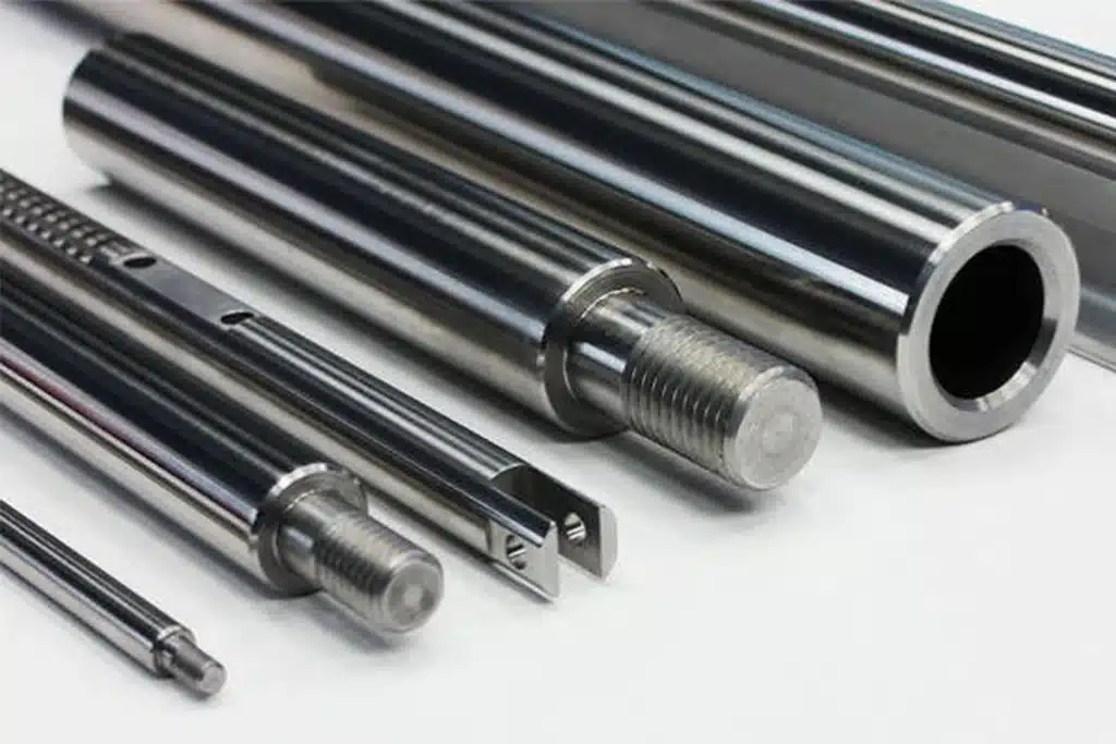
What Is a Robot Linear Shaft?
A robot linear shaft is typically a precision cylindrical component used to guide or support linear movement within a robotic mechanism. Working with compatible linear bearings and support structures, it provides a running surface that helps moving components travel along a defined path.
Its performance depends on more than the shaft itself. Dimensional accuracy, straightness, surface condition, bearing fit, and mounting alignment all contribute to the behavior of the assembled motion system.
What Is a Linear Shaft in a Robotic Motion System?
A linear shaft provides a straight running surface for compatible linear bearings, allowing a carriage, platform, or other moving component to travel along the shaft. Depending on the design, the shaft may be fixed while the bearing moves, or the shaft itself may move through a supported bearing assembly.
Unlike a motor or actuator, a linear shaft does not independently generate motion. Instead, it helps guide and support movement while working with bearings, drive mechanisms, and structural components.
In robotic positioning systems, handling equipment, and linear actuator assemblies, the shaft’s straightness, diameter tolerance, and surface finish can affect running smoothness and the accuracy of the guided motion.
Linear Shaft vs. Robot Joint Shaft
The terms linear shaft and robot joint shaft describe different functions and should not be treated as interchangeable.
A linear shaft typically supports guided linear movement, working with compatible bearings or other guiding elements. Its design focuses on factors such as straightness, diameter accuracy, surface finish, and bearing compatibility.
A robot joint shaft, by contrast, may refer to a shaft within a robot joint or joint module. Depending on the mechanism, it may transmit torque, support rotating components, or connect parts of a transmission assembly. Its design may therefore require particular attention to torsional strength, bending loads, fatigue resistance, and rotational accuracy.
The exact meaning of joint shaft depends on the robot’s mechanical design. When selecting or manufacturing a robot shaft, engineers should first identify its function and loading conditions rather than rely on the component name alone.
Linear Shaft vs. Linear Rail
Linear shafts and linear rails both guide linear movement, but they use different mechanical arrangements.
A linear shaft system typically uses a cylindrical shaft with a compatible linear bearing. It can offer a relatively simple design and flexible installation, depending on the support arrangement and application requirements.
A linear rail system uses a shaped rail and a compatible guide block, often with recirculating rolling elements. It can provide high rigidity and load capacity when properly selected and mounted, making it suitable for applications with demanding positioning and structural requirements.
The main differences involve bearing contact, load support, mounting requirements, and system configuration. Neither solution is universally better. The appropriate choice depends on the required accuracy, load direction, travel distance, available space, operating conditions, and cost.
For robotic applications, the key is to select a guiding system that meets the mechanical requirements of the entire assembly, rather than judging performance from the shaft or rail alone.

Why Are Linear Shafts Important in Robotics?
Linear shafts help establish and maintain the mechanical conditions required for controlled movement. Their geometry, stiffness, surface condition, and installation affect how moving components travel under load and how consistently they operate over time.
However, a linear shaft is only one part of the motion system. Its contribution to robot performance depends on how it works with bearings, supports, drive components, and the surrounding structure.
Providing a Reference for Controlled Linear Motion
A linear shaft provides a geometric guide for compatible bearings and moving components. Its straightness and installed position help define the path along which a carriage, platform, or other mechanism travels.
In robotic handling equipment, for example, a shaft may guide a component as it moves between pickup and placement positions. If the shaft is bent or incorrectly installed, the moving assembly may deviate from its intended path.
The shaft does not determine the entire motion trajectory on its own. The final path also depends on bearing alignment, mounting references, the machine structure, and the control system.
Supporting Loads and Maintaining Structural Stability
Depending on its arrangement, a linear shaft may experience radial loads, bending forces, or other loads transferred through the moving assembly. These forces can cause elastic deformation, particularly when the shaft is long or insufficiently supported.
Shaft diameter, material stiffness, support span, and load position all influence deflection. Excessive deflection can shift the position or orientation of a robot's end effector, affecting tasks such as part placement, inspection, or precision positioning.
It is also important to distinguish the load capacity of the shaft from that of the complete guiding system. Bearings, support blocks, mounting hardware, and the machine frame must all be suitable for the application.
Working with Bearings and Drive Components
A linear shaft typically works with compatible linear bearings and support structures, while a separate drive mechanism moves the assembly. Depending on the design, that drive may use an electric motor, pneumatic actuator, or another type of actuator.
The relationship between these components affects friction, clearance, and running resistance. An unsuitable shaft diameter or surface condition may interfere with bearing operation, while poor alignment can introduce uneven resistance during travel.
Reliable motion depends on compatibility across the assembly, not on the shaft specification alone. Shaft dimensions, bearing fit, lubrication, support alignment, and drive arrangement should therefore be considered together.
Contributing to Repeatable Robotic Movement
Robots often need to perform the same movement repeatedly, such as transferring components between fixed positions. A stable linear guiding arrangement helps the moving assembly follow a consistent path and reduces unwanted mechanical variation.
However, mechanical repeatability is not the same as the repeatability of the complete robot. Motor control, encoder feedback, backlash elsewhere in the mechanism, structural deformation, payload changes, and thermal conditions can all influence the final result.
A well-manufactured linear shaft supports consistent mechanical movement, but it cannot guarantee a specific robot positioning accuracy by itself. That result depends on the design, assembly, and performance of the complete system.

How Do Linear Shafts Affect Robot Performance?
Linear shafts can influence several aspects of robotic performance, from motion accuracy and running smoothness to vibration and long-term consistency. The effects depend on the shaft's manufacturing quality, dimensions, material, support arrangement, and interaction with other components.
For engineers, the important question is not simply whether a shaft is precise, but how its specific characteristics affect the motion system under actual operating conditions.
Motion Accuracy and Straightness
Shaft straightness affects how closely a moving bearing or carriage follows its intended path along the travel distance. If the shaft deviates from a straight line, that deviation can contribute to errors in the guided movement.
However, shaft straightness is different from diameter tolerance. Straightness describes the shaft's geometric deviation along its length, while diameter tolerance controls the permitted variation in its cross-sectional size. Both matter, but they influence motion in different ways.
The final linear accuracy also depends on installation alignment, support locations, bearing clearance, and the machine frame's reference surfaces. A shaft that meets its drawing specifications may still perform poorly if it is mounted incorrectly or integrated with unsuitable components.
Stiffness, Shaft Deflection, and Load Capacity
When a shaft carries a load, it may bend slightly under force. The amount of deflection depends on its diameter, material properties, unsupported length, support conditions, and the position and magnitude of the load.
For example, a long shaft supported only at one end behaves differently from a shaft supported at multiple points. A cantilevered arrangement may be more sensitive to bending, while additional supports can reduce deflection when properly designed and aligned.
Excessive shaft deflection can change the position of a moving platform or end effector, particularly when the load is offset from the guide. This may affect placement consistency or the results of precision operations.
Selecting a shaft requires evaluating the actual load and support arrangement together. Increasing shaft diameter may improve bending stiffness, but available space, moving mass, bearing compatibility, and drive requirements also need consideration.
Running Smoothness, Friction, and Clearance
The interaction between a shaft and its bearing has a direct effect on running resistance. Diameter accuracy, surface finish, bearing design, lubrication, and assembly alignment all influence how smoothly the components move.
Excessive clearance may allow unwanted movement or play, reducing mechanical stability. Conversely, a fit that is too tight can increase friction, restrict movement, complicate assembly, or cause problems when operating conditions change.
Surface defects or inconsistent shaft dimensions may also produce uneven contact between the shaft and bearing, contributing to irregular motion or premature wear.
The goal is to achieve the correct fit for the selected bearing and operating conditions, not simply to minimize every tolerance. Appropriate clearance and alignment help balance smooth movement, stability, and service life.
Vibration and Dynamic Response
During rapid acceleration, deceleration, or repeated back-and-forth movement, the shaft and its supporting structure respond to changing forces. Their mass, stiffness, support conditions, and natural frequencies influence how the system reacts to these loads.
If the shaft is insufficiently stiff or its supports are poorly arranged, the assembly may experience excessive vibration or take longer to settle after movement. These effects can interfere with high-speed positioning and may become more noticeable as payloads or operating speeds increase.
The solution depends on the complete mechanical design. Shaft dimensions, support spacing, mounting rigidity, moving mass, and drive profiles all influence dynamic behavior.
Improving shaft machining accuracy alone will not eliminate system vibration. The shaft must have suitable stiffness and support, and the assembled mechanism must be designed to operate within acceptable dynamic conditions.
Wear Resistance and Service Life
A linear shaft's surface interacts repeatedly with its bearing, making surface hardness, finish, lubrication, and contact conditions important to wear resistance. Contamination can introduce abrasive particles, while inadequate lubrication or unsuitable contact conditions can accelerate surface damage.
As wear develops, the shaft and bearing may no longer maintain their original fit. Increasing clearance can lead to more play, less consistent movement, or changes in running smoothness.
Material selection and surface treatment should match the bearing type, load, speed, environment, and maintenance requirements. Hardened or ground surfaces may be appropriate for certain applications, but the best solution depends on the complete design.
The service life of a linear motion system depends on both shaft durability and the condition of its bearings, lubrication, supports, and surrounding components. Selecting a wear-resistant shaft is valuable, but it does not remove the need for proper assembly and maintenance.
Positioning Consistency Over Repeated Cycles
A shaft may perform well during initial testing but behave differently after extended operation. Repeated loading, surface wear, thermal changes, loose mounting hardware, and variations in payload can gradually affect the movement system.
Stable shaft dimensions and surface quality help maintain the intended bearing fit. Proper support and secure mounting help prevent changes in alignment, while consistent manufacturing quality reduces unwanted variation between replacement parts or production batches.
These factors matter in robotic applications where the same movement must be repeated over many cycles. A small mechanical change may not be obvious during a short test but can become significant as wear or alignment changes accumulate.
Short-term positioning performance and long-term motion consistency are different requirements. A reliable design must account for both initial accuracy and the ability to maintain stable operation throughout the intended service conditions.

Key Design Factors for Robot Linear Shafts
Choosing a linear shaft involves more than selecting a diameter or material. Engineers need to consider the shaft's dimensions, support arrangement, end features, and mounting conditions in relation to the complete motion system.
A suitable shaft design balances stiffness, moving mass, bearing compatibility, installation requirements, and manufacturing cost.
Shaft Diameter and Length
Shaft diameter affects bending stiffness, while also influencing component weight, moving inertia, and the space required for installation. A larger diameter can improve stiffness under comparable conditions, but it may also increase mass and require larger bearings and supports.
Shaft length and support span are equally important. A long shaft with insufficient support may deflect significantly even when its diameter tolerance and straightness meet the drawing requirements.
Common options include a 10mm linear shaft, 12mm linear shaft, 16mm linear shaft, 20mm linear bearing shaft, 25mm linear shaft, and 30mm linear shaft. These are nominal size options, not fixed load ratings. The appropriate diameter depends on the actual load, unsupported length, bearing compatibility, and required stiffness.
Solid vs. Hollow Linear Shafts
Solid shafts provide a straightforward design and can offer substantial stiffness, but they generally contain more material than hollow shafts with the same outer diameter.
A hollow shaft can reduce mass, which may help limit the inertia of a moving assembly. However, its bending and torsional stiffness depend on both the inner and outer diameters, as well as the material and loading conditions.
The choice should reflect how the shaft is used. Reducing shaft weight is beneficial only when the resulting stiffness and strength remain sufficient for the application. Engineers should evaluate the complete cross-section and operating loads rather than assume that either solid or hollow construction is always superior.
Supported vs. Unsupported Shafts
The way a linear shaft is supported has a major influence on its deflection and structural stability. A shaft supported at multiple locations may resist bending differently from a cantilevered shaft or one with a long unsupported section.
The result depends on support spacing, load direction, shaft length, mounting rigidity, and where forces act on the assembly. Even a precisely manufactured shaft may bend excessively if its support arrangement is inadequate.
For this reason, shaft design and support design should be considered together. Support blocks, mounting surfaces, and fastening methods must provide suitable rigidity without introducing alignment errors or unwanted deformation.
Shaft Geometry and End Features
Robot linear shafts may require more than a uniform cylindrical surface. Depending on the assembly, their ends may include shoulders, steps, threads, retaining-ring grooves, or mounting interfaces.
These features help locate components, secure the shaft, and establish the required assembly position. However, changes in diameter and sharp transitions can create local stress concentrations, while threaded or grooved sections may introduce additional manufacturing and inspection requirements.
The design should also account for tool access, available assembly space, mating-component dimensions, and the required fits. Defining end features clearly on the drawing helps ensure that the shaft can be manufactured, inspected, and assembled as intended.
For custom shaft machining, CNC turning is commonly used to produce cylindrical profiles, shoulders, and threaded features. Additional machining or grinding may be required to meet specific dimensional and surface requirements.
Alignment and Mounting Conditions
A linear shaft must be installed in a way that allows its bearings and moving components to travel without unwanted binding or uneven resistance. Support positions, parallelism, mounting references, and the alignment of connected components all influence the final result.
Fastening forces can distort mounting structures, while temperature changes may affect dimensions or alignment. Small assembly errors can therefore introduce motion deviations even when individual parts meet their specified tolerances.
A compliant shaft drawing does not automatically guarantee accurate movement after assembly. Where the application requires close control of motion, the assembled system may need checks for alignment, straightness of travel, running resistance, or positioning performance.

Materials and Surface Treatments for Precision Robot Shafts
Material and surface treatment influence a linear shaft's stiffness, wear resistance, corrosion behavior, and manufacturing cost. The right combination depends on the operating environment, bearing contact, load, and required service conditions.
There is no single material or surface treatment suitable for every robotic application. The goal is to achieve the required mechanical and surface properties without adding unnecessary processing cost.
Carbon Steel and Hardened Steel Shafts
Carbon steel is a common option for linear shafts where strength, machinability, and cost are important considerations. Depending on the grade and application, heat treatment can improve the hardness and wear resistance of the working surface.
A harder surface may help a shaft withstand repeated contact with compatible bearings, but hardness alone does not determine performance. Core properties, surface quality, shaft geometry, and operating conditions also matter.
The required treatment should be specified according to the actual contact and loading conditions. Not every robot linear shaft needs the same steel grade or hardness level. Material selection and heat treatment should follow the functional requirements rather than a universal specification.
Stainless Steel Shafts for Corrosion Resistance
Stainless steel may be appropriate when shafts operate in humid environments, require frequent cleaning, or face exposure to corrosive substances. It can help reduce corrosion-related surface damage when the selected grade is suitable for the environment.
However, stainless steels vary in hardness, wear behavior, machinability, and cost. A grade selected primarily for corrosion resistance may not provide the same surface properties as a hardened shaft designed for repeated bearing contact.
Engineers should therefore consider both environmental exposure and mechanical requirements. In some applications, corrosion resistance is the priority; in others, wear resistance or dimensional stability may carry greater weight.
Surface Hardening, Grinding, and Chrome Plating
Surface treatments and finishing processes serve different purposes and should be selected accordingly.
· Surface hardening can improve resistance to wear and surface deformation when the material and treatment are suitable.
· Grinding can refine shaft diameter, roundness, and surface finish to meet the requirements of a particular bearing fit.
· Chrome plating may be used to improve selected surface properties, including corrosion or wear resistance, depending on the coating process and operating environment.
These processes are not interchangeable, and none is automatically required for every shaft. Heat treatment can affect dimensions, grinding adds manufacturing cost, and plating may change the final diameter or introduce coating-quality considerations.
The specified surface condition must match the bearing interface and the required finished dimensions. Material, treatment, and finishing allowances should be coordinated before production.
How to Match Shaft Materials to Robotic Applications
Material selection should begin with the shaft's working conditions rather than a preferred material name. Engineers should consider the load, movement frequency, operating environment, weight limits, expected maintenance, and available budget.
For example, a moving shaft in a lightweight positioning mechanism may place greater emphasis on mass and dynamic response. A fixed guide shaft operating under repeated bearing contact may place greater emphasis on surface durability and dimensional stability. Both still require adequate stiffness and compatibility with the selected bearing system.
Material and surface treatment should also be evaluated alongside shaft diameter, support arrangement, and machining requirements.
The best choice is the material and finish that meet the application's actual performance requirements—not necessarily the hardest, most corrosion-resistant, or most expensive option.

Precision Requirements for Robot Linear Shaft Manufacturing
Manufacturing precision affects how a linear shaft fits with its bearings, maintains its intended geometry, and performs under repeated movement. For robotic applications, the goal is not to make every dimension as tight as possible, but to control the characteristics that matter to the assembled system.
The required tolerances, surface condition, and inspection methods should be defined by the shaft's function and its interface with other components.
Diameter Tolerance and Bearing Fit
Diameter tolerance controls the permitted variation in a shaft's outside diameter. Because a linear bearing must fit and move correctly on the shaft, this dimension directly affects clearance, friction, and running behavior.
Tolerance designations such as h6, g6, and f6 describe different shaft tolerance zones under the applicable ISO system. They are not interchangeable specifications for every linear shaft. The appropriate designation depends on the bearing manufacturer's requirements, the intended fit, and the operating conditions.
It is also important to distinguish the shaft's diameter tolerance from the bearing's actual inside diameter and the resulting assembled clearance. These are separate factors that together determine the fit.
The correct fit balances smooth movement, acceptable clearance, reliable assembly, and manufacturing cost. Specifying an unnecessarily tight tolerance may increase production costs without improving the performance of the complete system.
Straightness, Roundness, and Cylindricity
These geometric characteristics control different aspects of a shaft's shape:
· Straightness controls how closely a specified line element or axis-related feature follows its intended straight geometry.
· Roundness controls the circular form of an individual cross-section.
· Cylindricity controls the overall form of a cylindrical surface, including deviations along its length and around its circumference.
These errors can affect bearing contact and movement in different ways. For example, excessive straightness deviation may influence the travel path, while poor roundness or cylindricity may contribute to inconsistent contact and clearance.
Measuring the shaft diameter alone cannot establish that all these characteristics are acceptable. Each geometric requirement must be specified and inspected according to the drawing, applicable standard, or validated application needs.
Surface Roughness and Hardness
Surface roughness affects how the shaft interacts with its bearing. An unsuitable surface may increase friction, accelerate wear, or interfere with smooth movement, depending on the bearing design and lubrication conditions.
Hardness serves a different purpose. It helps determine resistance to indentation and wear, but its effectiveness depends on the material, heat treatment, contact loads, and working environment.
The required surface finish and hardness should therefore be matched to the selected bearing and application. A surface specification suitable for one system may not be appropriate for another.
Surface finish and hardness should be treated as functional requirements, not isolated quality targets. Specific Ra or HRC values should be defined only when supported by the component drawing, bearing requirements, or verified engineering data.
CNC Turning, Grinding, and Secondary Machining
The manufacturing process depends on the shaft's geometry, material, tolerance requirements, and production volume.
· CNC turning is commonly used to produce the basic cylindrical profile, shaft shoulders, stepped diameters, and threaded features.
· Precision grinding can refine selected diameters and surface characteristics when tighter dimensional or geometric control is required.
· Secondary machining may be needed for grooves, end faces, cross-holes, mounting interfaces, or other application-specific features.
Not every shaft requires every process. Some designs can be produced efficiently through turning, while others need heat treatment, grinding, or additional operations to meet their functional requirements.
The manufacturing route should be selected from the finished-part requirements backward. This helps balance dimensional control, process capability, lead time, and cost without adding unnecessary operations.
Inspection and Quality Control
Inspection should focus on the characteristics that determine fit and function. Depending on the drawing, these may include shaft diameter, straightness, roundness, cylindricity, surface roughness, hardness, and critical end features.
Measurement methods and equipment must be appropriate for the specified tolerance. Reliable results also depend on suitable reference datums, measurement conditions, and inspection procedures.
Passing inspection as a single prototype does not automatically establish consistent quality across a production batch. Repeatable processes and appropriate in-process and final inspections help control variation between parts.
Where shaft-to-bearing compatibility is critical, dimensional inspection may need to be supplemented by a fit check or an assembled-motion test.
A useful quality-control plan verifies both the required part characteristics and their relevance to the assembled motion system.

Common Robot Linear Shaft Problems and Their Causes
Linear shaft problems can originate from the component itself, the support arrangement, assembly conditions, or the wider motion system. Identifying the actual cause is more effective than assuming every movement issue comes from insufficient machining precision.
Excessive Shaft Deflection
Possible causes: An undersized shaft, excessive unsupported length, inadequate support, or loads beyond the design conditions.
Potential effects: The moving assembly may shift from its intended position, lose motion accuracy, or experience increased vibration under load.
Prevention: Reassess shaft diameter, material stiffness, load position, support spacing, and mounting rigidity. Increasing shaft size may help, but the support structure and overall design must also be evaluated.
Binding, Friction, or Uneven Motion
Possible causes: An unsuitable shaft-to-bearing fit, misalignment, surface damage, contamination, or inadequate lubrication.
Potential effects: Running resistance may increase, movement may become irregular, and localized wear may develop.
Prevention: Check shaft dimensions against bearing requirements, inspect the running surface, verify mounting alignment, and confirm appropriate lubrication and cleanliness. If resistance changes along the travel distance, inspect the assembled guide system rather than only the shaft.
Excessive Clearance and Position Variation
Possible causes: Excessive initial clearance, bearing wear, shaft wear, or loose mounting components.
Potential effects: The moving assembly may develop unwanted play, reducing positional consistency and mechanical stability.
Prevention: Check shaft diameter, bearing condition, fastening security, and actual clearance in the assembled system. Replacing the shaft alone may not resolve the problem if the bearing or mounting structure is responsible.
Premature Wear and Surface Damage
Possible causes: Unsuitable surface hardness or finish, insufficient lubrication, contamination, or inappropriate contact conditions.
Potential effects: Wear can change the original fit, increase friction, and lead to more frequent maintenance or component replacement.
Prevention: Match material and surface treatment to the bearing interface and operating environment. Review lubrication, sealing, contamination control, and maintenance requirements as part of the complete system design.
Misalignment After Assembly
Possible causes: Incorrect support-block positions, uneven mounting surfaces, fastening-induced deformation, or inconsistent assembly references.
Potential effects: The bearing may experience uneven resistance or localized loading, while the moving component may deviate from its intended path.
Prevention: Verify mounting datums, support alignment, and parallelism during assembly. Check whether tightening fasteners changes the alignment, and validate movement after installation when required.
A shaft that passes dimensional inspection can still operate poorly when installed incorrectly. Separating component defects from assembly and system-design issues helps engineers identify the right corrective action and avoid unnecessary rework.

How to Select the Right Linear Shaft for a Robot
Selecting a linear shaft starts with the requirements of the motion system, not a standard diameter or material grade. Engineers should evaluate loading, motion accuracy, bearing compatibility, operating conditions, and manufacturing requirements before finalizing the specification.
Define the Load and Support Conditions
Start by identifying the loads acting on the shaft, including their direction, position, magnitude, and variation during operation. A shaft supporting a stationary guide may have different requirements from one that moves with a loaded platform.
Next, assess the shaft's unsupported length, support spacing, mounting arrangement, and allowable deflection. These factors influence stiffness and determine whether the shaft can maintain its intended position under load.
Do not determine load capacity from shaft diameter or material name alone. The shaft, bearings, supports, and mounting structure must work together under the actual operating conditions.
Determine the Required Motion Accuracy
Define the performance requirement before selecting tolerances. Depending on the application, the priority may be shaft straightness, dimensional accuracy, linear travel accuracy, or the repeatability of the complete mechanism.
These are different requirements. A shaft's geometric accuracy contributes to system performance, but bearing clearance, mounting alignment, frame stiffness, and drive control also affect the final result.
Select diameter tolerances according to the bearing specification and intended fit. Tighter tolerances are valuable only when they address a real functional requirement. Unnecessarily tight specifications can increase machining and inspection costs without delivering a meaningful performance benefit.
Choose the Material and Surface Condition
Material selection should reflect the shaft's load, wear exposure, corrosion risk, weight restrictions, and budget. Carbon steel or hardened steel may suit applications requiring wear resistance, while an appropriate stainless steel grade may be preferable in environments where corrosion is a concern.
Then determine whether the shaft needs heat treatment, precision grinding, or another surface treatment. Lubrication, contamination, and maintenance conditions should also influence the decision.
Choose the material and surface condition as a combined specification. The material must provide the required mechanical properties, and the manufacturing process must produce the finished dimensions and surface characteristics needed by the bearing system.
Check Shaft Geometry and Integration Requirements
Before requesting a quote, confirm the shaft's overall length, diameters, end features, and mounting interfaces. Include any required shoulders, threads, retaining-ring grooves, cross-holes, or other machined features.
Check these dimensions against the mating components, including linear bearings, support blocks, and drive assemblies. Consider tool access, assembly clearance, fastening methods, and the alignment of connected parts.
Clear drawings and interface requirements reduce the risk of manufacturing a shaft that meets its individual dimensions but cannot be installed or operated correctly.
Balance Precision, Cost, and Service Life
Not every robotic application requires the tightest available tolerances or the most extensive surface treatment. The appropriate specification is the one that meets the actual performance requirements reliably.
Focus tighter controls on critical dimensions and geometric features that affect bearing fit, travel accuracy, stiffness, or wear. Less critical features may allow more economical tolerances when the design permits.
Also consider the cost of maintenance, downtime, inspection, and replacement—not just the initial part price.
A cost-effective linear shaft is one that meets the required performance consistently without unnecessary manufacturing complexity. A well-defined specification helps balance precision, service life, and total operating cost.

Applications of Linear Shafts in Robotic Systems
Linear shafts are used in robotic systems that rely on guided linear movement. Their role varies with the mechanism, but common considerations include motion stability, load support, bearing compatibility, and consistent movement over repeated cycles.
Pick-and-Place and Material Handling Robots
Pick-and-place and material handling equipment often moves components between defined pickup, transfer, and placement positions. Where a linear shaft guides a carriage or moving platform, its geometry and support arrangement can influence the stability of that movement.
Payload changes are also important. A shaft and bearing arrangement that performs adequately under a light load may deflect more when carrying heavier parts or operating at higher acceleration.
The shaft specification should account for both the required travel and the loads encountered during repeated handling cycles. The exact role of the shaft depends on the equipment's mechanical layout.
Cartesian and Gantry Robots
Cartesian and gantry robots use linear motion along multiple axes. Depending on the design, shafts may serve as guides for moving assemblies that travel horizontally, vertically, or along an extended span.
Longer travel distances can increase the importance of support spacing, shaft deflection, and alignment. Different axes may also carry different loads: a vertical axis, for example, may have different support and loading requirements from a horizontal axis.
For these systems, shaft selection should be evaluated separately for each axis and then checked against the assembled mechanism.
Maintaining accurate movement over a long travel distance requires appropriate shaft sizing, support design, and alignment—not simply a high-precision shaft.
Linear Actuator and Robotic Positioning Modules
Linear positioning modules combine guiding components with a drive mechanism and a moving platform. A linear shaft may guide the platform through compatible bearings, while a separate component provides the driving force.
These components have distinct functions. A linear shaft provides a guiding or supporting surface; a linear rail guides movement through a rail-and-block arrangement; and a ball screw, where used, converts rotary input into linear motion. An actuator may integrate several of these elements into one assembly.
During integration, engineers need to verify interface dimensions, bearing fit, support rigidity, alignment, and available installation space. The selected shaft must suit both the guiding function and the module's operating conditions.
Specialized Robotic Equipment
Linear shafts may also be used in laboratory automation, automated inspection equipment, and other precision positioning systems where components must travel along a controlled path.
In these applications, requirements may include smooth low-speed movement, consistent positioning, compatibility with cleaning procedures, or resistance to environmental exposure. The priorities depend on the equipment and its operating conditions.
Not every robot mechanism uses a linear shaft. Rotary joints and other motion systems may rely on different shaft types, bearings, or transmission components.
The relevant question is whether the equipment uses a shaft-based linear guide and, if so, which mechanical requirements that shaft must satisfy.

Custom Robot Linear Shaft Machining and Manufacturing
Custom robot linear shafts often require specific dimensions, bearing interfaces, end features, and surface characteristics that standard components may not provide. Successful manufacturing starts with clear engineering requirements and a process suited to the finished part.
From CAD Drawings to Machining Requirements
Manufacturers typically need a technical drawing or CAD file that defines the shaft's dimensions, material, tolerances, surface requirements, and critical interfaces.
Particular attention should be given to bearing-fit dimensions, geometric tolerances, and end features. Missing specifications can lead to incompatible fits, unexpected clearance, or assembly difficulties.
If the shaft must work with an existing linear bearing or support assembly, provide the relevant component specifications and interface requirements.
A complete drawing should define not only the shaft's shape, but also the characteristics that determine how it fits and functions in the assembly.
Selecting the Right Machining Process
The machining route depends on the shaft's material, geometry, tolerances, surface requirements, and production quantity.
CNC turning is commonly used for cylindrical profiles, stepped diameters, shoulders, and threads. Precision grinding may be added when particular diameters or surface characteristics require closer control. Additional machining processes can produce grooves, holes, and specialized mounting interfaces.
Some shafts can be manufactured efficiently with turning alone, while others require several operations to meet their specifications.
The right process is the one that achieves the required functional characteristics with reliable quality and reasonable cost—not a fixed sequence applied to every shaft.
Prototype Validation and Production Consistency
Prototype manufacturing allows engineers to check critical dimensions, bearing compatibility, installation clearances, and assembly feasibility before committing to larger quantities.
Once the design is validated, production requires consistent machining processes and appropriate inspection methods to control variation between parts. Critical dimensions and geometric characteristics should be checked against the drawing rather than judged by appearance alone.
Where necessary, a fit check or assembled-motion test can help confirm that the shaft performs as intended with its mating components.
A successful prototype demonstrates initial feasibility; repeatable production demonstrates that the required quality can be maintained across the order.
What to Include in a Shaft Machining RFQ
A clear request for quotation (RFQ) helps manufacturers assess feasibility, select the appropriate process, and provide a more accurate quote. Include the following information where applicable:
· Drawings or CAD files: Part geometry, dimensions, and revision information.
· Material requirements: Material grade, required certificates, and heat treatment, if specified.
· Critical tolerances: Shaft diameters, fits, and other controlled dimensions.
· Geometric and surface requirements: Straightness, roundness, cylindricity, surface roughness, or hardness where required.
· End features and interfaces: Threads, shoulders, grooves, holes, and mounting details.
· Order quantity: Prototype quantity and expected production volume, if known.
· Inspection requirements: Required reports, measurement records, or other quality documentation.
· Operating conditions: Load, bearing type, corrosion exposure, lubrication, or other application details that affect material and process selection.
The more clearly the functional requirements are defined, the easier it is to identify manufacturing risks before production begins.
Robot Linear Shaft FAQs
What Is the Difference Between a Robot Shaft and a Linear Shaft?
A robot shaft is a broad term for shaft components used in robotic mechanisms, including transmission shafts and shafts within rotary joints. A linear shaft is specifically used to guide or support linear movement, typically in combination with compatible bearings. The required geometry and performance characteristics depend on the shaft's function.
How Does a Linear Shaft Affect Robot Accuracy?
Shaft straightness, dimensional accuracy, surface condition, and bearing fit can affect the guided motion path and mechanical stability. However, the robot's final accuracy also depends on installation alignment, structural rigidity, drive components, and control systems. A precise shaft alone cannot guarantee a specific system-level accuracy.
Is a Larger Linear Shaft Always Better for a Robot?
No. A larger diameter can improve bending stiffness, but it may also increase weight, moving inertia, space requirements, and cost. The appropriate size depends on the load, unsupported length, support arrangement, bearing compatibility, and required motion performance.
Does Every Precision Linear Shaft Need to Be Hardened and Ground?
No. Heat treatment and grinding depend on the required wear resistance, bearing interface, dimensional tolerances, and surface finish. Some applications may require both processes, while others can meet their functional requirements through a simpler manufacturing route.
What Shaft Tolerance Is Suitable for Linear Bearings?
The suitable tolerance depends on the bearing model, specified fit, operating conditions, and required clearance. Designations such as h6 may be appropriate for certain applications, but they should not be treated as a universal requirement. Always confirm the shaft tolerance against the bearing manufacturer's specifications and the assembly design.
How Do You Prevent a Linear Shaft from Bending?
Evaluate shaft diameter, material stiffness, unsupported length, load magnitude and position, and support arrangement. Reducing the support span or adding suitable supports may help, depending on the design. The shaft and mounting structure should be assessed together rather than relying on diameter alone.
Can a Custom-Machined Shaft Be Used in a Robotic System?
Yes. A custom-machined shaft can be designed for a specific robotic mechanism, provided its dimensions, material, tolerances, surface condition, and interfaces meet the application requirements. Prototype inspection and, where appropriate, assembly testing help verify compatibility before production.
What Information Is Needed to Request a Custom Robot Shaft Quote?
Provide a technical drawing or CAD file, material specification, order quantity, critical dimensions and tolerances, surface treatment requirements, and inspection needs. Details about the bearing, support arrangement, load, and operating environment are also useful when they affect the shaft's design or manufacturing process.
