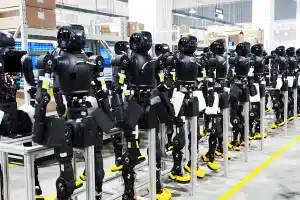
Modern robots are built through a combination of mechanical engineering, electronics, materials science, and precision manufacturing. Whether it is an industrial robot, a collaborative robot, a medical robot, or a humanoid system, every machine depends on accurately manufactured components working together as a single integrated platform.
A typical robot contains structural frames, joints, housings, shafts, gears, bearings, sensors, controllers, and end effectors. Each component must meet specific requirements for strength, weight, dimensional accuracy, surface quality, and assembly compatibility. Even small deviations in critical parts can affect motion accuracy, repeatability, vibration behavior, and long-term reliability.
The manufacturing process usually begins with robot design and DFM evaluation, followed by prototype development, material selection, precision machining, surface finishing, quality inspection, and finally assembly and production validation. As robots become more compact, lightweight, and intelligent, the requirements for manufacturing precision continue to increase.
This guide explains the complete process of robot component manufacturing, from the initial design stage to full-scale production, and explores the technologies, quality controls, and engineering considerations that enable modern robotic systems to achieve high performance.
The Typical Robot Manufacturing Flow
Robot Design
Robot manufacturing begins long before the first part is machined. The design stage determines the performance, reliability, weight, assembly efficiency, and manufacturing cost of the final robot. A well-designed component can be produced consistently and assembled accurately, while a poorly designed component may create machining difficulties, tolerance stack-up problems, excessive weight, or unnecessary production expense.
Modern robots are typically designed around four interconnected objectives: structural strength, motion performance, precision, and manufacturability. Engineers must balance these factors from the earliest stages of development because improvements in one area can affect another. For example, increasing stiffness by adding material may improve accuracy but also increase weight and motor load. Reducing weight may improve dynamic performance but require more complex machining or stronger materials.
Robot System Architecture
The first step is defining the robot’s overall architecture. Designers determine the number of axes, workspace, payload capacity, speed requirements, and control strategy. These decisions influence the size and arrangement of major components such as the base, links, joints, gearboxes, motors, and end effectors.
For industrial robots, the architecture often prioritizes high payload and repeatability. Collaborative robots emphasize safety, lightweight construction, and smooth motion. Humanoid robots require compact joints, low inertia, and efficient integration of actuators and sensors. Each architecture creates different manufacturing requirements and different challenges for precision component production.

Structural Design
Structural design focuses on how loads are transmitted through the robot. Frames, arms, brackets, and housings must withstand static loads, dynamic forces, vibration, and repeated motion cycles.
Key considerations include:
- Bending stiffnessof arms and links
- Torsional rigidityof joint structures
- Fatigue resistanceunder repeated motion
- Weight distributionacross the robot
- Mounting interfacesfor motors, reducers, and sensors
Engineers frequently use finite element analysis (FEA) to identify areas of high stress and optimize material distribution. The goal is to achieve sufficient stiffness while minimizing unnecessary mass.
Motion and Kinematic Design
Robots are fundamentally motion systems, so the design of joints and link geometry directly affects accuracy and responsiveness. The position of each axis determines the robot’s reachable workspace, singularity behavior, and load distribution.
Designers must consider:
- Axis arrangement
- Joint range of motion
- Center of gravity location
- Gear reduction requirements
- Backlash control
- Dynamic stability
In high-speed applications, even small increases in rotating inertia can significantly affect acceleration and energy consumption. This is why many robotic systems use lightweight structural components and compact drive assemblies.
Thermal Management
Motors, drives, and electronic systems generate heat during operation. If thermal expansion is not considered during design, critical dimensions can change and reduce positioning accuracy.
Effective robot design may include:
- Heat-dissipating housings
- Ventilation paths
- Cooling manifolds
- Thermally stable mounting surfaces
- Separation of heat sources from precision components
For precision robotic systems, thermal behavior is often as important as mechanical strength.

Assembly-Oriented Design
A component that is easy to machine but difficult to assemble can still create major production problems. Good robot design considers the assembly process from the beginning.
Common assembly-oriented practices include:
- Using standardized fasteners
- Providing adequate tool access
- Adding alignment features
- Reducing the number of unique parts
- Designing repeatable locating surfaces
- Minimizing complex adjustment procedures
These decisions can substantially reduce assembly time and improve production consistency.
Designing for Precision Manufacturing
One of the most important aspects of robot design is ensuring that the geometry can be manufactured accurately. Features such as deep narrow pockets, extremely thin walls, inaccessible internal corners, and excessive tolerance requirements can increase machining difficulty and cost.
Experienced design teams evaluate:
- Wall thickness stability
- Tool accessibility
- Datum structure
- Tolerance allocation
- Surface finish requirements
- Inspection feasibility
In many robotics projects, the success of later manufacturing stages depends on decisions made during this initial design phase.
The Importance of Early Manufacturing Consideration
A common misconception is that manufacturing begins after the design is completed. In reality, manufacturing considerations should be integrated into the design process from the start. Early collaboration between design engineers and manufacturing engineers helps identify potential issues before prototypes are built.
When design, machining, assembly, and inspection requirements are evaluated together, robot components can achieve better performance, lower production risk, faster development cycles, and more predictable scaling from prototype to mass production.

Design for Manufacturing (DFM)
Design for Manufacturing (DFM) is the process of creating robot components that can be produced efficiently, consistently, and economically without compromising functional performance. In robotics, DFM is especially important because many parts require tight tolerances, complex geometries, lightweight structures, and precise assembly interfaces. A design that performs well in CAD but is difficult to machine or inspect can lead to higher costs, longer lead times, and increased production risk.
For robot manufacturers, DFM is not simply a cost-reduction exercise. It is a method of improving manufacturability, dimensional stability, assembly reliability, and production scalability. Decisions made during the DFM stage often determine whether a prototype can transition smoothly into volume production.
Simplifying Machining Geometry
One of the first goals of DFM is reducing unnecessary machining complexity. Features such as deep narrow cavities, extremely small internal radii, undercuts, and inaccessible pockets can require specialized tooling or additional machining operations.
Common DFM improvements include:
- Using standard cutter-accessible corner radii
- Avoiding excessively deep pockets
- Reducing unnecessary 3D surface transitions
- Designing features that can be machined in fewer setups
- Maintaining adequate tool clearance around critical areas
These adjustments can significantly improve machining efficiency while maintaining the required functionality.
Optimizing Wall Thickness
Robotics frequently demands lightweight components, but overly thin walls can create manufacturing and performance problems. Thin sections are more susceptible to deformation during machining, vibration during cutting, thermal distortion, and dimensional instability after material removal.
Good DFM practice aims to maintain:
- Uniform wall thickness where possible
- Sufficient rigidity around mounting points
- Additional reinforcement near threaded holes
- Smooth transitions between thick and thin sections
For structural robot parts, a balanced wall-thickness strategy often provides better overall performance than aggressively minimizing material everywhere.
Standardizing Holes and Threads
Robots contain large numbers of fasteners, locating pins, bearings, and assembly interfaces. Using multiple unique hole sizes and thread specifications increases tooling changes, inspection complexity, and assembly errors.
DFM recommendations include:
- Using standardized thread series
- Minimizing the number of unique fastener sizes
- Applying consistent counterbore and countersink dimensions
- Using common bearing and dowel-pin fits
Standardization simplifies both manufacturing and maintenance throughout the robot’s lifecycle.

Managing Tolerances Correctly
A common mistake in robotic component design is applying extremely tight tolerances to every dimension. This increases machining time, inspection effort, and production cost without necessarily improving system performance.
Effective DFM focuses tight tolerances only on functionally critical features, such as:
- Bearing seats
- Joint alignment surfaces
- Gearbox mounting interfaces
- Encoder positioning features
- Precision datum surfaces
Non-critical dimensions should use more reasonable tolerance ranges. This approach improves manufacturability while maintaining robot accuracy where it matters most.
Designing for Stable Workholding
Every machined component must be securely fixtured during production. Parts with insufficient clamping surfaces or highly irregular shapes can be difficult to hold without distortion.
DFM considerations include:
- Providing stable reference surfaces
- Avoiding unsupported thin extensions
- Including temporary fixturing areas when necessary
- Designing symmetrical features that simplify setup
Stable workholding is essential for maintaining dimensional accuracy across multiple machining operations.
Considering Inspection Early
A feature that is difficult to measure is often difficult to control in production. DFM should evaluate how critical dimensions will be inspected before manufacturing begins.
Engineers should consider:
- Accessibility for probes and measuring tools
- Clear datum references
- Geometric tolerance verification methods
- CMM measurement feasibility
- Repeatability of inspection setups
Early inspection planning helps prevent costly redesigns later in the development process.

Reducing Assembly Complexity
Manufacturing efficiency is only part of DFM. Robot components must also be assembled repeatedly with minimal variation.
Designs that support efficient assembly often include:
- Self-locating features
- Alignment bosses or dowel holes
- Clear orientation references
- Accessible fastener locations
- Reduced part count
- Modular subassemblies
Reducing assembly complexity improves production throughput and lowers the probability of installation errors.
Balancing Performance and Cost
The best DFM solution is rarely the simplest design or the cheapest design. Instead, it is the design that achieves the required robotic performance with the lowest total manufacturing risk.
| Design Choice | Potential Impact |
|---|---|
| Extremely Thin Walls | Lower weight but higher distortion risk |
| Ultra-Tight Tolerances | Higher precision but significantly higher cost |
| Complex Organic Geometry | Better aesthetics but longer machining time |
| Multiple Custom Fasteners | Higher assembly complexity |
| Standardized Interfaces | Better production consistency |
Experienced robotics manufacturers evaluate these trade-offs before production begins.
Why DFM Is Critical for Robotics
Robots combine precision motion, lightweight structures, repeated dynamic loading, and tight assembly requirements. Because of this combination, manufacturing issues that might be acceptable in general industrial equipment can become serious performance problems in robotic systems.
A well-executed DFM process helps ensure that robot components are easier to machine, easier to inspect, easier to assemble, and more consistent across production batches. It also reduces the likelihood of redesigns during prototype validation and supports a smoother transition from development to full-scale manufacturing.

Prototype Development
Before a robot enters production, it typically goes through multiple rounds of prototype development. Prototyping is the stage where design assumptions are tested against physical reality. It allows engineers to verify whether components fit together correctly, whether motion systems operate smoothly, and whether the structure can withstand real operating conditions.
In robotics, prototype development is particularly important because robots combine precision mechanics, electronic integration, dynamic motion, and complex assemblies. A CAD model may appear correct, but issues such as interference, insufficient stiffness, cable routing problems, thermal expansion, vibration, and assembly difficulty often become visible only after physical parts are manufactured and tested.
The Purpose of Robot Prototypes
Robot prototypes serve several engineering objectives:
- Validate the mechanical design
- Verify assembly compatibility
- Test motion performance
- Evaluate structural rigidity
- Confirm sensor and actuator integration
- Identify manufacturing risks
- Refine tolerances and interfaces
- Reduce the likelihood of costly production changes
The earlier a problem is discovered, the less expensive it is to correct.
Types of Robot Prototypes
Different prototype stages focus on different aspects of the robot.
Functional Prototype
A functional prototype verifies basic motion and mechanical operation. Components may not use final production materials or surface finishes, but the prototype allows engineers to test kinematics, joint movement, and control behavior.
Engineering Validation Prototype
This stage evaluates whether the design meets performance requirements such as accuracy, payload capacity, stiffness, and thermal stability. Parts are often manufactured using production-intent processes to generate realistic test data.
Appearance Prototype
For collaborative robots, service robots, and commercial products, appearance prototypes help evaluate external design, ergonomics, and user interaction.
Production Validation Prototype
Production validation prototypes are built using processes that closely match planned mass production. The goal is to confirm that manufacturing, assembly, and quality control procedures can be repeated consistently.

Prototype Manufacturing Methods
Robotics prototypes often combine multiple manufacturing technologies depending on the development objective.
| Technology | Typical Use |
|---|---|
| 3D Printing | Concept models, lightweight testing, complex geometry verification |
| CNC Machining | Functional metal components, housings, brackets, precision interfaces |
| Turning | Shafts, bushings, couplings |
| Sheet Metal Fabrication | Covers, enclosures, support structures |
| Soft Tooling | Limited-run molded plastic parts |
Many robotics projects use 3D printing for early concept validation and CNC machining for later engineering verification when dimensional accuracy and material properties become critical.
What Engineers Evaluate During Prototyping
Component Fit and Assembly
Engineers verify that mounting holes, locating features, bearings, gears, and housings align correctly. Even small positional deviations can create assembly difficulties in precision robotic systems.
Motion Performance
Joint movement is tested for smoothness, backlash, friction, and range of motion. High-speed robots may also be evaluated for vibration and dynamic stability.
Structural Strength
Arms, links, and frames are subjected to representative loads to confirm that deflection remains within acceptable limits.
Thermal Behavior
Motors, drives, and electronics generate heat during operation. Prototype testing helps identify potential thermal expansion or cooling issues before production.
System Integration
Mechanical, electrical, and software systems are validated together. Cable routing, connector access, sensor placement, and maintenance accessibility are often refined during this stage.
The Role of Iteration
Robotics prototypes are rarely perfect on the first attempt. Most successful projects go through multiple iterations.
Each iteration reduces uncertainty and improves the maturity of the design. Changes made during prototyping are usually far less expensive than changes made after production tooling, supply chain commitments, and assembly processes have been established.
Prototype Development and Manufacturing Readiness
Beyond validating the design, prototypes also help evaluate manufacturing readiness. Engineers can determine whether machining strategies are stable, whether inspection methods are practical, and whether assembly operations can be performed efficiently.
For complex robot components such as gearbox housings, servo motor housings, precision joints, and lightweight structural links, prototype builds often reveal opportunities to simplify machining operations, improve datum structures, or reduce assembly time.
Why Prototyping Is Essential in Robotics
Robots operate in environments where accuracy, repeatability, and reliability are critical. A prototype allows engineers to validate not only individual components but also the interaction between mechanical, electrical, and control systems.
By combining physical testing with iterative refinement, prototype development reduces technical risk, improves product performance, and creates a more reliable foundation for the transition from engineering development to full-scale production.

Material Selection
Material selection is one of the most important engineering decisions in robot manufacturing. The chosen material influences weight, stiffness, strength, thermal stability, wear resistance, corrosion resistance, machining behavior, and overall system cost. A material that performs well in one robotic application may be unsuitable in another, so selection must be based on the specific functional requirements of the component.
In modern robotics, engineers rarely choose a material based on a single property. Instead, they evaluate how the material affects motion performance, structural integrity, manufacturing feasibility, assembly reliability, and long-term durability.
Balancing Weight and Stiffness
For moving robot arms and links, reducing mass is often a priority because lower inertia allows faster acceleration and reduced motor load. However, excessive weight reduction can decrease stiffness and increase deflection during operation.
Engineers therefore evaluate the strength-to-weight ratio and stiffness-to-weight ratio rather than simply minimizing weight. Components that experience dynamic motion, such as articulated arms, wrists, and humanoid joints, often require a careful balance between lightweight construction and structural rigidity.
Considering Load Conditions
Different robot components experience different types of loading.
| Component Type | Primary Load Consideration |
|---|---|
| Structural Frames | Bending and torsion |
| Joints | Repeated cyclic loading |
| Shafts | Torsional and fatigue loads |
| Gearbox Housings | Alignment and stiffness |
| End Effectors | Impact and gripping forces |
High-load applications require materials capable of maintaining dimensional accuracy under stress, while lightweight collaborative robots may prioritize reduced mass and lower inertia.
Thermal Stability
Robots often operate continuously, generating heat from motors, drives, and electronics. Temperature changes can cause components to expand or contract, affecting alignment and positioning accuracy.
For precision robotic systems, engineers evaluate:
- Coefficient of thermal expansion
- Heat dissipation capability
- Dimensional stability across operating temperatures
- Compatibility with cooling strategies
Thermal considerations are especially important in semiconductor equipment, medical robotics, and high-precision automation systems.

Wear and Friction Requirements
Components such as bushings, sliding surfaces, guide mechanisms, and certain joint interfaces experience repeated contact and friction.
Material selection for these areas focuses on:
- Wear resistance
- Surface hardness
- Coefficient of friction
- Lubrication compatibility
- Resistance to particle generation
In clean environments such as semiconductor manufacturing, minimizing wear debris can be as important as maximizing service life.
Corrosion and Environmental Resistance
Robots may operate in factories, laboratories, food-processing facilities, outdoor environments, or medical settings. Exposure to moisture, cleaning agents, chemicals, or sterilization processes can significantly influence material selection.
Engineers assess:
- Corrosion resistance
- Chemical compatibility
- Cleaning and sterilization requirements
- Environmental contamination risks
- Long-term surface stability
For medical and food-related applications, material selection often includes additional regulatory and hygiene considerations.
Manufacturing Feasibility
A material must not only meet performance requirements; it must also be practical to manufacture. Some materials offer excellent mechanical properties but are significantly more difficult to machine, finish, or inspect.
Manufacturing-related considerations include:
- Machinability
- Tool wear
- Heat generation during cutting
- Surface finish capability
- Dimensional stability after machining
- Availability of suitable finishing processes
For complex robot housings and precision joints, manufacturing feasibility can strongly influence the final material decision.

Cost and Production Volume
The optimal material for a prototype may not be the optimal material for production. Engineers often evaluate material choices differently depending on expected production volume.
| Development Stage | Typical Priority |
|---|---|
| Concept Prototype | Speed and ease of fabrication |
| Engineering Validation | Representative mechanical performance |
| Production Launch | Consistency and manufacturability |
| Mass Production | Total cost and supply stability |
Material selection should therefore consider both current development needs and future production requirements.
Typical Material Selection Priorities
| Requirement | Selection Priority |
|---|---|
| Lightweight Robot Arm | Low mass, high stiffness |
| High-Load Joint | Strength, fatigue resistance |
| Precision Gearbox Housing | Dimensional stability, machinability |
| Medical Robot Component | Biocompatibility, corrosion resistance |
| Semiconductor Robot Part | Cleanliness, thermal stability |
| Sliding Mechanism | Wear resistance, low friction |
A System-Level Decision
In advanced robotics, material selection is rarely an isolated decision. The choice for one component can affect motor sizing, payload capacity, energy consumption, thermal management, assembly methods, and manufacturing processes throughout the entire robot.
Successful robotic systems therefore treat material selection as a system-level engineering decision, balancing performance, manufacturability, reliability, and cost to achieve the desired operational outcome.

Manufacturing Technologies
Robot manufacturing relies on multiple production technologies because different components have different functional requirements. Structural frames require rigidity, joints demand precision, shafts need accurate concentricity, and complex housings often contain internal features that are difficult to machine with conventional methods.
Among the most important technologies used in robotics are CNC machining, CNC turning, grinding, and EDM. These processes are frequently combined within a single robotic assembly to achieve the required accuracy, surface quality, and performance.
CNC Machining
CNC machining is one of the primary manufacturing methods for robot components. It is widely used for structural parts that require high dimensional accuracy, complex geometries, and reliable repeatability.
Typical robot components produced by CNC machining include:
- Robot arms and links
- Joint housings
- Gearbox housings
- Motor mounts
- Sensor brackets
- Base structures
- Precision mounting plates
Modern robotic systems often require multi-axis machining to create complex surfaces, angled features, and integrated mounting interfaces in a single setup. Reducing the number of setups helps maintain geometric accuracy and positional consistency across critical features.
For lightweight robotic structures, CNC machining is also used to remove unnecessary material while preserving stiffness. This allows engineers to optimize weight without sacrificing structural performance.
The main advantages of CNC machining in robotics are:
- High dimensional precision
- Excellent repeatability
- Capability for complex geometries
- Compatibility with a wide range of materials
- Suitable for both prototypes and production runs
As robots become more compact and integrated, CNC machining continues to play a central role in manufacturing precision structural components.
CNC Turning
CNC turning is used for rotationally symmetric robot components that require precise concentricity and dimensional control. Many motion-transmission elements in robotic systems depend on accurately turned features.
Common turned components include:
- Drive shafts
- Joint shafts
- Couplings
- Bushings
- Spacers
- Threaded adapters
- Bearing seats
In robotic joints, shaft accuracy directly affects bearing alignment, gear engagement, and overall motion smoothness. Poor concentricity can introduce vibration, uneven loading, and premature wear.
Advanced turning centers can perform turning, milling, drilling, and threading in a single operation, reducing handling and improving positional accuracy between features.
Key benefits of CNC turning include:
- Excellent roundness and concentricity
- Efficient production of cylindrical components
- High repeatability
- Reduced setup time for rotational parts
- Consistent bearing and sealing interfaces
For high-performance robotic systems, precision turning is often essential for maintaining reliable motion transmission.

Grinding
Grinding is used when machining alone cannot achieve the required precision or surface quality. Many robotic assemblies contain interfaces that demand tighter tolerances than standard milling or turning operations can consistently provide.
Grinding is commonly applied to:
- Bearing journals
- Precision shafts
- Joint locating surfaces
- Gearbox reference faces
- Hardened components
- High-precision alignment features
Robot joints often rely on accurately ground surfaces to maintain alignment and minimize friction. Even small deviations can affect repeatability and long-term performance.
Grinding also improves surface roughness, which can be important for sliding interfaces, bearing fits, and sealing surfaces.
The main advantages of grinding are:
- Extremely high dimensional accuracy
- Superior surface finish
- Excellent roundness and cylindricity
- Capability for hardened materials
- Improved fit and alignment quality
In precision robotics, grinding is frequently used as a finishing operation after turning or machining to achieve final critical dimensions.
EDM (Electrical Discharge Machining)
EDM is used for features that are difficult or impossible to produce efficiently with conventional cutting tools. Instead of mechanically removing material, EDM removes material through controlled electrical discharges.
This process is particularly useful for:
- Complex internal cavities
- Sharp internal corners
- Deep narrow slots
- Precision keyways
- Hardened materials
- Intricate joint components
- Specialized tooling features
For robotics, EDM is often selected when component geometry requires features that would otherwise need multiple specialized machining operations.
Two common forms are:
- Wire EDM– suitable for precise profiles, slots, and contour cutting.
- Sinker EDM– suitable for cavities and complex three-dimensional internal features.
The advantages of EDM include:
- Ability to machine very hard materials
- Excellent precision
- Minimal cutting force
- Capability for intricate geometries
- Reduced risk of mechanical deformation
EDM is generally slower than conventional machining, so it is typically reserved for high-precision or highly complex features where its unique capabilities provide a clear engineering advantage.
Together, CNC machining, turning, grinding, and EDM form the foundation of precision robot component manufacturing. Each process addresses a different set of geometric and performance requirements, and the most advanced robotic assemblies often combine all four technologies to achieve the necessary accuracy, reliability, and functional integration.
Sheet Metal Fabrication
Sheet metal fabrication is widely used for robot enclosures, protective covers, control cabinets, support structures, and lightweight mounting assemblies. Unlike CNC machining, which removes material from a solid block, sheet metal fabrication forms components from flat metal sheets through cutting, bending, punching, and joining operations.
In robotic systems, sheet metal components are often selected when the design requires large surface areas, moderate structural strength, reduced weight, and cost-efficient production. Collaborative robot bases, mobile robot chassis, equipment enclosures, and automation frames frequently combine sheet metal structures with precision-machined components.
Typical fabrication operations include:
- Laser cutting
- CNC punching
- Press braking
- Welding
- Riveting
- Fastener insertion
Designers must account for bend allowances, material springback, corner reliefs, and assembly tolerances during development. Proper DFM practices help ensure that formed parts maintain dimensional consistency and fit accurately with machined interfaces.
The main advantages of sheet metal fabrication in robotics are:
- Efficient production of large structural panels
- Lower material waste
- Reduced component weight
- Good scalability for medium- and high-volume production
- Easy integration of mounting features and cable-management openings
Because robotic systems often require both precision and structural coverage, sheet metal parts are commonly used together with CNC-machined brackets, housings, and mounting plates.

3D Printing
3D printing has become an important tool for robot prototype development and low-volume production. It enables engineers to manufacture complex geometries directly from digital models without dedicated tooling.
In robotics, 3D printing is frequently used for:
- Concept models
- Functional prototypes
- Custom sensor mounts
- Cable-routing components
- Lightweight covers
- Experimental end effectors
- Low-volume specialized parts
Different additive manufacturing technologies serve different purposes:
| Technology | Typical Robotics Use |
|---|---|
| FDM | Fast concept validation |
| SLA | High-detail appearance parts |
| SLS | Functional engineering components |
| MJF | Durable low-volume production parts |
The greatest advantage of 3D printing is design freedom. Internal channels, lattice structures, organic shapes, and integrated features that would be difficult to machine conventionally can often be produced directly.
However, engineers must also consider limitations such as surface finish, dimensional accuracy, anisotropic mechanical properties, and production speed. For many robotics projects, 3D printing is used during early development, while final production components are manufactured using machining, molding, or other production-oriented processes.
Injection Molding
Injection molding is the preferred manufacturing method for high-volume plastic robot components. Once the mold has been created, the process can produce large quantities of parts with excellent repeatability and low per-unit cost.
Common injection-molded robot components include:
- External covers
- Control housings
- Cable guides
- Sensor enclosures
- Connector supports
- Protective caps
- Lightweight internal structures
Because tooling investment is significant, injection molding is usually introduced after the design has been validated through prototyping.
Successful molding design requires attention to:
- Uniform wall thickness
- Draft angles
- Rib reinforcement
- Gate placement
- Sink mark prevention
- Parting-line location
- Ejection strategy
For robotic products manufactured in large quantities, injection molding provides high consistency, fast production cycles, and excellent cosmetic quality. It is especially valuable for collaborative robots, service robots, and commercial robotic products where appearance and repeatability are important.
Assembly
Assembly is the stage where individual manufactured components become a functional robotic system. Even when every part is produced accurately, poor assembly practices can reduce precision, create alignment problems, and affect long-term reliability.
Robot assembly typically combines:
- Mechanical subassemblies
- Bearings and shafts
- Gearboxes and reducers
- Servo motors
- Sensors and encoders
- Cable harnesses
- Control electronics
- Protective covers and enclosures
Critical assembly considerations include:
- Alignment of bearing and shaft interfaces
- Controlled fastener torque
- Backlash adjustment
- Cable routing and strain relief
- Cleanliness of precision surfaces
- Verification of moving clearances
- Functional testing of actuators and sensors
For high-precision robotic joints, assembly often requires dedicated fixtures and measurement procedures to maintain concentricity and positional accuracy.
After mechanical assembly, robots typically undergo a series of validation steps:
- Motion testing
- Calibration
- Accuracy verification
- Repeatability testing
- Load testing
- Safety checks
- System integration validation
In advanced robotics manufacturing, assembly is not treated as a simple final operation. It is a precision integration process that directly influences the robot’s performance, reliability, and consistency in production.

Surface Finishing
Surface finishing is a critical stage in robot manufacturing because it affects far more than appearance. The surface condition of a component can influence corrosion resistance, wear resistance, friction, electrical conductivity, cleanliness, thermal behavior, and long-term durability.
Robot components often operate in demanding environments that involve repeated motion, vibration, temperature changes, exposure to lubricants or cleaning agents, and strict precision requirements. As a result, surface finishing is typically selected based on functional performance requirements rather than cosmetic considerations alone.
Why Surface Finishing Matters in Robotics
Many robot parts are machined from aluminum, stainless steel, titanium, or engineering alloys. After machining, the surface may contain tool marks, residual stresses, oxidation, or other conditions that can affect performance.
Proper finishing can help:
- Improve corrosion resistance
- Increase wear resistance
- Reduce friction
- Enhance fatigue life
- Improve electrical properties
- Facilitate cleaning and maintenance
- Provide a consistent visual appearance
For precision robotic assemblies, surface finish can also influence the behavior of bearing interfaces, sliding mechanisms, seals, and mating surfaces.
Anodizing
Anodizing is widely used for aluminum robot components, including arms, housings, brackets, and structural frames. The process creates a controlled oxide layer that becomes an integral part of the material surface.
Benefits of anodizing include:
- Improved corrosion resistance
- Enhanced surface hardness
- Better wear resistance
- Electrical insulation properties
- Reduced risk of surface oxidation
- Consistent cosmetic appearance
Hard anodizing is often selected for components that experience repeated contact or abrasion, while decorative anodizing may be used for visible exterior surfaces on collaborative or commercial robots.
Powder Coating
Powder coating provides a durable protective layer for sheet metal structures, enclosures, frames, and external covers. The coating is applied as a dry powder and then cured to form a continuous protective surface.
In robotic applications, powder coating offers:
- Good impact resistance
- Strong corrosion protection
- Excellent edge coverage
- Wide color selection
- Durable exterior finish
Because of its toughness and environmental resistance, powder coating is commonly used on mobile robot chassis, equipment cabinets, and industrial automation structures.

Polishing
Polishing is used when a smooth surface is required for appearance, reduced friction, or improved cleanliness. Depending on the application, polishing may range from a brushed industrial finish to a near-mirror surface.
Polished surfaces can help:
- Reduce friction in sliding interfaces
- Minimize particle retention
- Improve cleanability
- Enhance aesthetic quality
- Improve performance in certain sealing applications
Medical robots, laboratory automation systems, and visible exterior components often require higher polishing standards than general industrial equipment.
Electroplating
Electroplating deposits a metallic coating onto the surface of a component to modify its functional properties. Different plating materials are selected depending on the application requirements.
Common objectives include:
- Improving corrosion resistance
- Increasing surface hardness
- Enhancing electrical conductivity
- Reducing contact resistance
- Improving wear performance
Connector components, electrical interfaces, and certain precision mechanical parts may use specialized plating systems to achieve the required performance characteristics.
Surface Finish and Precision Interfaces
In robotics, surface finish is often closely related to dimensional accuracy. Critical interfaces such as bearing seats, shaft journals, guide surfaces, and sealing areas may require both tight tolerances and controlled surface roughness.
Excessively rough surfaces can increase friction and wear, while overly smooth surfaces may affect lubrication behavior in some applications. Engineers therefore specify surface roughness values based on the functional requirements of the interface.

Cleanliness Requirements
For semiconductor, medical, and laboratory robotics, surface finishing must also support cleanliness requirements. Finishes that trap particles or are difficult to clean can create contamination risks.
In these environments, manufacturers may select finishing processes that:
- Reduce particle adhesion
- Minimize surface porosity
- Improve chemical resistance
- Support repeated cleaning or sterilization
Selecting the Appropriate Finish
The choice of surface finish depends on the component’s function within the robot.
| Component Requirement | Typical Finishing Consideration |
|---|---|
| Aluminum Structural Arm | Anodizing |
| Industrial Enclosure | Powder Coating |
| Visible Exterior Housing | Decorative anodizing or polishing |
| Sliding Interface | Polishing or low-friction treatment |
| Electrical Contact Component | Electroplating |
| Cleanroom Robot Component | Cleanable corrosion-resistant finish |
Surface Finishing as a Functional Engineering Process
In advanced robotics manufacturing, surface finishing is treated as a functional engineering process rather than a final cosmetic step. The selected finish can directly affect reliability, maintenance requirements, environmental resistance, and operational performance.
By matching the finishing process to the specific demands of each robot component, manufacturers can improve durability, maintain precision over time, and ensure that robotic systems continue to perform consistently in their intended operating environments.

Quality Inspection
Quality inspection is one of the most critical stages in robot manufacturing because robotic systems depend on precise alignment, repeatable motion, and consistent component performance. A dimensional error that may be acceptable in general industrial equipment can significantly affect robot accuracy, vibration behavior, gear engagement, or joint reliability.
Inspection is not limited to checking whether a part matches a drawing. It is a comprehensive process that verifies dimensions, geometric relationships, surface condition, material conformity, assembly compatibility, and functional performance throughout the manufacturing cycle.
Why Inspection Is Critical for Robotics
Robots contain multiple interconnected motion systems. Errors can accumulate through bearings, shafts, housings, reducers, and mounting interfaces, creating what is known as a tolerance stack-up. Even small deviations in individual components can reduce overall positioning accuracy.
Critical robot assemblies often require inspection of:
- Bearing seat diameters
- Shaft concentricity
- Joint alignment surfaces
- Gearbox mounting interfaces
- Encoder positioning features
- Parallelism and perpendicularity of mating surfaces
- Assembly datum structures
Maintaining these relationships is essential for achieving reliable motion control and repeatability.
Dimensional Inspection
Dimensional inspection verifies that individual features meet specified tolerances. Common measurements include:
- Overall dimensions
- Hole diameters
- Thread dimensions
- Slot widths
- Wall thickness
- Center-to-center distances
- Critical mounting interfaces
For robotic components, dimensional inspection is often performed using calipers, micrometers, bore gauges, height gauges, and precision measurement systems depending on the required accuracy.

Geometric Tolerance Inspection
Many robotic parts require more than simple dimensional control. Geometric tolerances ensure that features are correctly oriented and positioned relative to one another.
Important geometric characteristics include:
- Flatness
- Parallelism
- Perpendicularity
- Position tolerance
- Concentricity
- Cylindricity
- Runout
These controls are especially important for robot joints, rotating assemblies, and precision gearbox interfaces where alignment directly affects performance.
CMM Inspection
Coordinate Measuring Machines (CMMs) are widely used for high-precision robotic components. A CMM can measure complex geometries and verify multiple dimensions and geometric tolerances within a single inspection program.
CMM inspection is commonly used for:
- Complex machined housings
- Multi-axis components
- Precision joint structures
- Gearbox housings
- Servo motor mounting interfaces
- Prototype validation
- First article inspection (FAI)
Because many robot parts contain features on multiple planes and orientations, CMM inspection provides a highly effective method for verifying overall geometric accuracy.
Surface Roughness Inspection
Surface finish can influence friction, wear, sealing performance, and bearing behavior. Inspection therefore includes verification of specified surface roughness values.
Typical applications include:
- Bearing seats
- Shaft journals
- Sliding interfaces
- Sealing surfaces
- Polished functional areas
Surface roughness testers help ensure that finishing processes have achieved the required functional condition.

Material Verification
Inspection also confirms that the correct material has been used for each component. Depending on the application, verification may include:
- Material certificates
- Chemical composition analysis
- Hardness testing
- Heat-treatment verification
- Traceability records
Material verification is particularly important for high-load joints, medical robot components, semiconductor equipment parts, and safety-critical structures.
Assembly Inspection
After individual components pass dimensional inspection, assembly inspection verifies that the assembled mechanism functions correctly.
Assembly checks may include:
- Bearing preload
- Shaft alignment
- Backlash measurement
- Fastener torque verification
- Rotational smoothness
- Clearance validation
- Cable routing inspection
For precision robotic joints, assembly inspection often determines whether the final system will achieve its target repeatability.
Functional Testing
Functional testing evaluates how the component or assembly performs under operating conditions. Depending on the robot type, testing may include:
- Motion cycle testing
- Load testing
- Accuracy verification
- Repeatability testing
- Vibration analysis
- Thermal performance testing
- Sensor and encoder validation
Functional testing provides confirmation that the manufactured assembly performs as intended in real robotic applications.

Traceability and Documentation
Advanced robotics manufacturing increasingly requires full traceability. Inspection records may include:
- Material batch information
- Machining process records
- Measurement data
- Calibration status of inspection equipment
- Nonconformance reports
- Corrective action records
- Final inspection reports
Traceability is especially important for medical, aerospace, semiconductor, and high-reliability industrial robotics.
Inspection Throughout the Manufacturing Process
Effective quality control does not occur only at the end of production. Robotic component manufacturers often use incoming inspection, in-process inspection, and final inspection to detect issues as early as possible.
| Inspection Stage | Primary Objective |
|---|---|
| Incoming Inspection | Verify raw materials and purchased components |
| In-Process Inspection | Monitor machining and manufacturing accuracy |
| Final Inspection | Confirm complete conformity before shipment |
| Assembly Inspection | Validate integration and fit |
| Functional Testing | Verify operational performance |
Quality Inspection as a Performance Guarantee
In robotics, quality inspection is not merely a compliance activity. It is a performance assurance process that helps ensure components assemble correctly, move accurately, withstand operational loads, and maintain reliability over time.
By combining dimensional measurement, geometric verification, material validation, assembly inspection, and functional testing, manufacturers can reduce production risk and deliver robotic systems with the precision and consistency required for modern automation applications.

Supply Chain Management
Robot manufacturing is rarely completed by a single process or a single production cell. A typical robotic system may include CNC-machined housings, turned shafts, ground precision surfaces, sheet metal structures, molded plastic components, purchased bearings, motors, sensors, cables, and electronic assemblies. Coordinating these elements requires effective supply chain management.
In robotics, supply chain management is not only about purchasing parts. It is the process of ensuring that materials, components, manufacturing operations, inspections, assembly activities, and delivery schedules are synchronized so that the final product can be produced consistently and on time.
The Complexity of Robotics Supply Chains
Compared with many conventional industrial products, robots often involve:
- Multiple material types
- High-precision machined components
- Custom assemblies
- Specialized electronic components
- Long-lead-time purchased parts
- Prototype and production variants
- Frequent engineering changes
As robot designs become more sophisticated, managing the interaction between these elements becomes increasingly important.
Coordinating Multiple Manufacturing Processes
A single robot assembly may require several different manufacturing technologies before final assembly can begin.
Supply chain management ensures that each process is completed in the correct sequence and that parts move through production without unnecessary delays.
Poor coordination can result in:
- Idle assembly operations
- Missed delivery dates
- Increased inventory costs
- Repeated setup changes
- Production bottlenecks
- Quality traceability gaps
Material Procurement
Raw material selection and procurement have a direct impact on manufacturing stability. Robotics manufacturers must ensure that the correct material grade, certification, and specification are available before production begins.
Key considerations include:
- Material availability
- Lead time
- Batch consistency
- Certification requirements
- Heat treatment status
- Dimensional stock sizes
For high-performance robotic components, material substitutions without proper engineering review can create significant performance and reliability risks.

Managing Long-Lead Components
Many robotic systems depend on purchased components such as:
- Servo motors
- Reducers
- Precision bearings
- Linear guides
- Encoders
- Sensors
- Industrial connectors
These items may have significantly longer lead times than machined components. Effective supply chain planning identifies long-lead items early and aligns procurement schedules with prototype and production milestones.
Inventory Strategy
Robotics manufacturers must balance inventory levels carefully. Excess inventory increases storage cost and capital usage, while insufficient inventory can interrupt production.
Common strategies include:
| Strategy | Primary Objective |
|---|---|
| Safety Stock | Protect against supply disruptions |
| Buffer Inventory | Absorb demand fluctuations |
| Kanban Replenishment | Support continuous production |
| Just-in-Time Delivery | Reduce inventory carrying cost |
The appropriate strategy depends on production volume, demand variability, and supplier reliability.
Engineering Change Management
Prototype development and early production often involve design revisions. Supply chain management must ensure that obsolete parts are controlled and updated revisions are released correctly.
Important controls include:
- Revision tracking
- Change approval procedures
- Updated drawings and specifications
- Inventory segregation
- Supplier notification
- Assembly documentation updates
Without disciplined change management, mixed revisions can create assembly problems and field failures.
Quality and Traceability Across the Supply Chain
Supply chain management and quality management are closely connected. Manufacturers must be able to trace materials and components throughout the production process.
Traceability may include:
- Material batch numbers
- Supplier identification
- Heat treatment records
- Inspection reports
- Assembly lot numbers
- Final product serial numbers
This is particularly important for medical robots, semiconductor equipment, aerospace applications, and safety-critical automation systems.

Global Supply Chain Considerations
Many robotics projects involve international customers, suppliers, and manufacturing partners. Global supply chain management must consider:
- Import and export regulations
- Customs documentation
- Transportation lead times
- Tariffs and duties
- Regional compliance requirements
- Logistics risk management
Planning these factors early helps prevent delays during prototype shipments and production deliveries.
Supporting the Transition to Production
As a robot moves from prototype to production, supply chain requirements change significantly. Prototype builds may prioritize speed and flexibility, while production builds require repeatability, cost control, and reliable delivery.
Manufacturers typically focus on:
- Supplier qualification
- Process standardization
- Capacity planning
- Production scheduling
- Inventory optimization
- Long-term procurement agreements
These activities help ensure that production can scale without sacrificing quality or delivery performance.
Supply Chain Management as a Manufacturing Capability
In advanced robotics manufacturing, supply chain management is a core operational capability rather than a purely administrative function. It directly affects lead time, production efficiency, quality consistency, scalability, and customer delivery performance.
By coordinating materials, processes, suppliers, inspections, and logistics, an effective supply chain enables robotic manufacturers to move from engineering development to stable production while maintaining the precision and reliability required by modern automation systems.

Prototype to Production
One of the most challenging phases in robot manufacturing is transitioning from a working prototype to stable production. A prototype may successfully demonstrate motion, functionality, and system integration, but producing the same performance consistently across dozens, hundreds, or thousands of units requires additional engineering, process control, and manufacturing planning.
For robotics manufacturers, the prototype-to-production stage is where design validation, manufacturing capability, quality control, supply chain management, and production readiness come together. The goal is not only to build a robot that works, but to establish a repeatable process that delivers consistent accuracy, reliability, and delivery performance.
The Typical Transition Path
Most robotics projects progress through several development stages before full-scale production.
Each stage has a different objective.
| Stage | Primary Objective |
|---|---|
| Concept Prototype | Validate basic design ideas |
| EVT (Engineering Validation Test) | Verify functionality and performance |
| DVT (Design Validation Test) | Confirm design meets specifications |
| PVT (Production Validation Test) | Validate manufacturing and assembly processes |
| Mass Production | Deliver consistent production output |
Engineering Validation (EVT)
During EVT, engineers focus on whether the robot performs as intended.
Typical activities include:
- Motion testing
- Payload verification
- Joint performance evaluation
- Sensor integration testing
- Thermal analysis
- Software and control validation
Manufacturing processes may still be flexible at this stage, and design changes are relatively common.
Design Validation (DVT)
DVT confirms that the design can meet its final specifications under realistic operating conditions.
Testing may include:
- Accuracy and repeatability measurement
- Environmental testing
- Vibration testing
- Long-cycle durability testing
- Safety verification
- Compliance evaluation
By the end of DVT, major design changes should be minimized.

Production Validation (PVT)
PVT is the critical bridge between engineering and manufacturing. The objective is to verify that the planned production process can consistently produce conforming robot assemblies.
PVT evaluates:
- Machining process stability
- Fixture repeatability
- Assembly workflow
- Inspection procedures
- Operator instructions
- Cycle time
- Yield rate
- Supply chain readiness
Many manufacturing issues that are not visible during prototype builds become apparent during PVT.
Freezing the Manufacturing Process
Before mass production begins, manufacturers typically establish a process freeze. This means that critical aspects of the manufacturing process are formally controlled.
Items commonly frozen include:
- Approved drawings and revisions
- Material specifications
- Machining programs
- Tooling and fixtures
- Inspection plans
- Assembly procedures
- Test protocols
- Supplier lists
Process freezing helps maintain consistency across production batches.
Scaling Manufacturing Capacity
A prototype may be built with highly skilled technicians and flexible scheduling. Production requires a different approach.
Manufacturers must consider:
- Machine capacity
- Tool life management
- Fixture availability
- Operator training
- Production scheduling
- Inventory planning
- Quality staffing
- Assembly line balancing
Scaling successfully requires both technical preparation and operational planning.
Managing Tolerance Consistency
One of the most important challenges during production ramp-up is maintaining consistent tolerances across all manufactured parts.
Manufacturers often implement:
- Statistical process control (SPC)
- In-process inspection
- Tool wear monitoring
- Machine calibration schedules
- First article inspection
- Capability studies
For robotic joints, gearbox housings, and precision shafts, maintaining process capability is essential for preserving assembly accuracy.

Assembly Readiness
Transitioning to production also requires assembly optimization. Prototype assemblies may involve manual adjustments that are impractical at production volumes.
Engineers often refine:
- Alignment features
- Fastener accessibility
- Cable routing
- Subassembly structure
- Torque specifications
- Inspection checkpoints
- Functional test procedures
Reducing assembly variability improves throughput and product consistency.
Common Challenges During Ramp-Up
Robotics manufacturers frequently encounter:
- Thin-wall deformation during production machining
- Variation in supplier components
- Fixture-induced distortion
- Assembly tolerance stack-up
- Surface finish inconsistencies
- Long-lead purchased parts
- Unexpected thermal effects
- Lower-than-expected production yield
Identifying these issues early during PVT can prevent significant delays after launch.
The Role of NPI (New Product Introduction)
NPI provides the structured framework for moving a robot from development into production. It coordinates engineering, manufacturing, quality, supply chain, and operations teams.
Typical NPI activities include:
- DFM review
- Process planning
- Tooling preparation
- Supplier qualification
- Pilot builds
- Inspection planning
- Risk assessment
- Production documentation
A well-executed NPI process reduces launch risk and shortens the time required to achieve stable production.
From a Successful Prototype to a Successful Product
A prototype demonstrates that a robot can work. Production demonstrates that the robot can be manufactured repeatedly with consistent quality. The transition between these two stages requires disciplined engineering, validated processes, reliable suppliers, controlled inspections, and scalable manufacturing operations.
By treating prototype-to-production as a structured engineering process rather than a simple increase in quantity, robotics manufacturers can reduce risk, improve delivery performance, and achieve a more reliable path to commercial production.

Dakings Rapid Robotics Component Manufacturing Services
Robotic systems demand a combination of high precision, structural reliability, lightweight design, and production consistency. Components such as joint housings, gearbox housings, servo motor mounts, structural links, shafts, and mounting brackets often require tight dimensional control and stable manufacturing processes to ensure accurate motion and repeatable performance.
Dakings Rapid provides precision manufacturing services for robotics and automation applications, supporting customers from early prototype development through low-volume and production manufacturing. The focus is on components that require accurate machining, controlled tolerances, reliable surface quality, and assembly-ready interfaces.
Precision CNC Machining for Robotics
CNC machining is widely used for robotic structural and motion-related components. Dakings Rapid manufactures parts such as:
- Robot arm structures
- Joint housings
- Gearbox housings
- Motor mounting plates
- Precision brackets
- Sensor mounting interfaces
- Base structures
For complex robotic geometries, multi-axis machining helps reduce setup changes and maintain positional accuracy between critical features.
High-Precision Turning and Grinding
Rotational components play a critical role in robotic motion systems. Dakings Rapid supports the manufacturing of:
- Joint shafts
- Drive shafts
- Couplings
- Bushings
- Bearing seats
- Precision cylindrical interfaces
Where tighter tolerances and improved surface quality are required, Turning and Grinding operations can be applied to achieve accurate bearing fits, concentricity, and alignment surfaces for precision robotic assemblies.
Thin-Wall and Lightweight Structural Components
Modern collaborative and humanoid robots often require lightweight structures with high stiffness. Thin-wall machining introduces challenges such as deformation, vibration, and dimensional instability during production.
Dakings Rapid addresses these challenges through:
- Optimized machining strategies
- Controlled material removal sequences
- Stable workholding methods
- Stress-management considerations
- Process verification during prototype builds
This approach helps maintain dimensional stability while supporting lightweight robotic designs.

Prototype Manufacturing and NPI Support
Robotics projects frequently require multiple design iterations before production release. Dakings Rapid supports prototype development with:
- Functional prototype machining
- Engineering validation builds
- Small-batch prototype production
- DFM feedback
- Assembly fit verification
- Process optimization for production transfer
Early collaboration during the prototype stage helps identify manufacturing risks and improve production readiness.
Surface Finishing for Robot Components
Robot components often require surface treatments that improve durability and environmental resistance. Available finishing options include:
- Anodizing
- Powder coating
- Polishing
- Electroplating
- Sandblasting
- Brushing
Finishing selection is based on the functional requirements of the component, including wear resistance, corrosion protection, electrical properties, and cosmetic appearance.
Quality Control and Inspection
Precision robotic assemblies depend on accurate component geometry. Dakings Rapid applies inspection procedures that may include:
- Dimensional measurement
- Geometric tolerance verification
- CMM inspection
- Surface roughness measurement
- Material verification
- Assembly fit checks
Inspection processes help ensure that critical interfaces such as bearing seats, shaft fits, and gearbox mounting surfaces meet specified requirements.
Production Scalability
Robotics manufacturing often begins with prototypes and progresses to larger production volumes. Dakings Rapid supports this transition through:
- Low-volume production runs
- Pilot production builds
- Process standardization
- Supply chain coordination
- Production scheduling
- Consistent quality control procedures
By combining prototype support, precision machining, finishing, inspection, and production management, Dakings Rapid provides manufacturing capabilities aimed at the requirements of robotics, automation equipment, medical robotics, semiconductor automation, and other precision motion-control applications.

Common Manufacturing Challenges
Robot manufacturing combines precision machining, lightweight structural design, dynamic motion requirements, and complex assembly interfaces. As a result, manufacturers often face challenges that are less critical in conventional industrial products but can significantly affect robotic performance.
Successful production depends not only on machining accuracy but also on controlling deformation, alignment, surface quality, process consistency, and assembly behavior throughout the entire manufacturing cycle.
Thin-Wall Deformation
Many modern robots use lightweight structures to reduce inertia and improve motion efficiency. Components such as arm links, joint housings, and structural frames may contain thin walls and large internal pockets.
During machining, these parts can deform due to:
- Cutting forces
- Residual material stress
- Heat generation
- Insufficient workholding support
- Uneven material removal
Excessive deformation can cause dimensional errors, assembly interference, and reduced structural stiffness. Manufacturers often address this through optimized machining sequences, stable fixturing, and stress-management strategies.
Complex Multi-Axis Geometry
Robot joints and integrated housings frequently contain features on multiple planes, curved surfaces, and angled interfaces. Maintaining accurate relationships between these features can be challenging.
Common difficulties include:
- Setup alignment
- Tool accessibility
- Geometric tolerance control
- Collision avoidance in machining
- Consistent feature positioning across batches
Multi-axis machining reduces the number of setups but requires precise programming and process control.
High-Precision Assembly Alignment
Robotic systems rely on accurate alignment between shafts, bearings, reducers, motors, and encoders. Even small positional errors can affect motion smoothness and repeatability.
Assembly challenges often involve:
- Bearing concentricity
- Shaft runout
- Gearbox alignment
- Encoder positioning
- Backlash control
- Tolerance stack-up across multiple components
Because robotic motion systems are interconnected, alignment issues in one component can influence the performance of the entire assembly.

Thermal Effects During Manufacturing
Heat generated during machining can temporarily expand both the workpiece and the cutting tool. For precision robotic components, this can lead to dimensional variation if not properly controlled.
Thermal-related challenges include:
- Size drift during long machining cycles
- Variation between morning and afternoon production
- Tool expansion
- Workpiece temperature differences
- Post-machining dimensional changes
Manufacturers often use controlled machining parameters, coolant management, and process stabilization to minimize thermal influence.
Balancing Weight and Strength
Lightweight design is desirable for robotic motion performance, but reducing material too aggressively can compromise stiffness and fatigue life.
Engineers must balance:
- Mass reduction
- Structural rigidity
- Dynamic stability
- Fatigue resistance
- Manufacturing feasibility
This trade-off is particularly important in collaborative robots and humanoid robots, where both low inertia and high structural integrity are required.
Surface Finish Consistency
Robot components often contain sliding interfaces, bearing seats, sealing surfaces, and visible exterior parts. Variations in surface finish can affect friction, wear, lubrication behavior, and appearance.
Challenges may include:
- Tool wear affecting roughness
- Inconsistent polishing results
- Uneven anodizing appearance
- Coating thickness variation
- Surface contamination before finishing
Consistent finishing requires controlled process parameters and proper preparation before treatment.
Batch-to-Batch Repeatability
A prototype may meet specifications, but maintaining the same quality across production batches is often more difficult.
Repeatability challenges can arise from:
- Tool wear
- Fixture variation
- Machine calibration drift
- Material batch differences
- Operator variation
- Environmental conditions
Statistical process control and in-process inspection are commonly used to monitor production stability.
Supply Chain Variability
Robotic assemblies frequently incorporate purchased components such as bearings, reducers, motors, sensors, and connectors. Variations in lead time, quality, or specification can disrupt production.
Manufacturers must manage:
- Supplier qualification
- Incoming inspection
- Revision control
- Inventory planning
- Alternative sourcing strategies
Effective supply chain management is essential for maintaining production schedules and product consistency.
Scaling from Prototype to Production
Processes that work well for a small number of prototype parts may not be suitable for larger production volumes.
Common scaling challenges include:
- Long machining cycle times
- Manual assembly adjustments
- Insufficient fixture capacity
- Complex inspection procedures
- Low production yield
- Extended lead times
Production scaling often requires process optimization, dedicated tooling, standardized work instructions, and improved automation.
Managing Manufacturing Risk
Because robotic systems integrate mechanical, electrical, and control technologies, manufacturing risk must be managed across multiple disciplines. The most successful robotics manufacturers identify potential problems early through DFM review, prototype validation, process planning, and structured quality control.
By addressing deformation, alignment, thermal behavior, surface quality, process repeatability, and supply chain stability together, manufacturers can improve production reliability and support the consistent performance required by modern robotic systems.